Mazda CX-5 Service & Repair Manual: Fuel Pump Unit
Purpose, Function
-
Supplies fuel in the fuel tank to the high pressure fuel pump.
-
Based on the control signal from the PCM, the fuel pump operates by the operation of the fuel pump relay and the fuel pump control module.
Construction
2WD
-
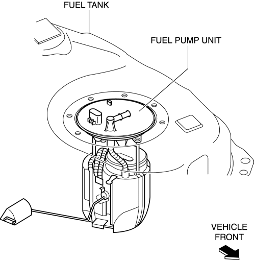
The fuel pump unit is installed to the fuel tank.
-
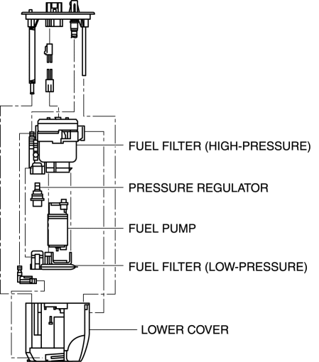
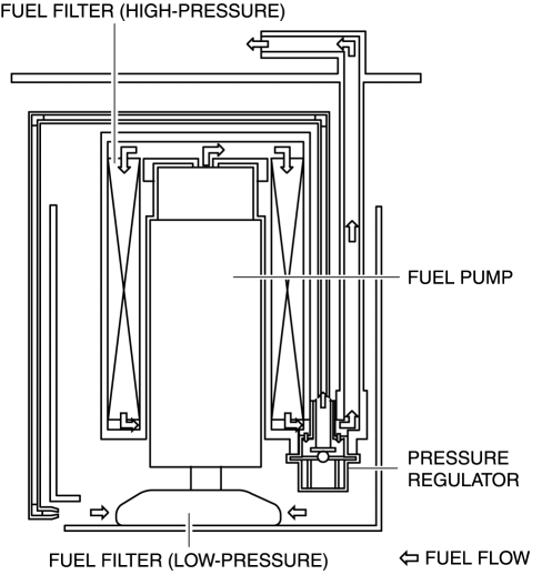
The fuel pump unit consists of a fuel pump, fuel filter (low-pressure) fuel filter (high-pressure), pressure regulator, and lower cover.
AWD
-
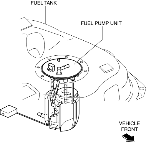
The fuel pump unit is installed to the fuel tank.
-
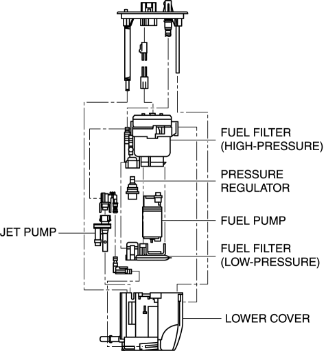
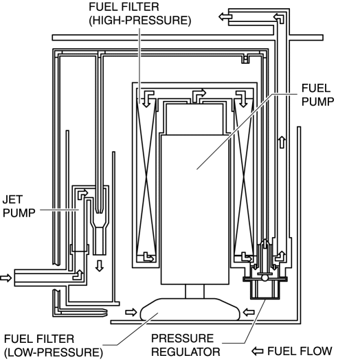
The fuel pump unit consists of a fuel pump, fuel filter (low-pressure) fuel filter (high-pressure), pressure regulator, lower cover, and jet pump.
Operation
2WD
-
Based on the control signal from the PCM, the fuel pump suctions fuel in the lower cover and pumps it to the high pressure fuel pump. After fuel is sufficiently filtered through the fuel filter (low-pressure) and fuel filter (high-pressure), fuel pressure is adjusted to approx. 430 kPa {4.38 kgf/cm2, 62.4 psi}
by the pressure regulator.
AWD
-
Based on the control signal from the PCM, the fuel pump suctions fuel in the lower cover and pumps it to the high pressure fuel pump. After fuel is sufficiently filtered through the fuel filter (low-pressure) and fuel filter (high-pressure), fuel pressure is adjusted to approx. 430 kPa {4.38 kgf/cm2, 62.4 psi}
by the pressure regulator.
-
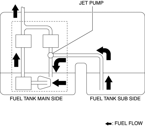
Positions the venturi pipe (jet pump) in the return path from the pressure regulator and sends fuel from the fuel tank sub side to the main side using vacuum generated in that area.
-
For fuel pump control details, refer to CONTROL SYSTEM..
Fail-safe
-
Function not equipped.
 Fuel Pump Unit Removal/Installation
WARNING:
Fuel is very flammable liquid. If fuel spills or leaks from the pressurized
fuel system, it will cause serious injury or death and facility breakage. Fuel
can also irritate skin ...
 Fuel Shut Off Valve Inspection
U.S.A. And CANADA
NOTE:
The fuel shut-off valve cannot be removed and inspected as it is built into
the fuel tank.
1. Perform the fuel tank inspection..
If there is any malfu ...
Other materials:
Slide Motor Removal/Installation
WARNING:
Handling a side air bag improperly can accidentally operate (deploy) the
air bag, which may seriously injure you. Read the service warnings/cautions
in the Workshop Manual before handling the front seat (side air bag integrated)..
If the sliding mechanisms on both side ...
Fuel Draining Procedure
WARNING:
Fuel line spills and leakage from the pressurized fuel system are dangerous.
Fuel can ignite and cause serious injury or death and damage. To prevent this,
complete the following inspection with the engine stopped.
Fuel is very flammable liquid. If fuel spills or leaks ...
Cargo Compartment Light Removal/Installation
1. Disconnect the negative battery cable..
2. To prevent scratches or damage, affix protective tape to the position shown
in the figure.
CAUTION:
If a flathead screwdriver is inserted into the gap between the cargo compartment
light and trunk side trim, the trunk side trim could int ...
