Mazda CX-5 Service & Repair Manual: Front Side Frame Removal [Panel Replacement]
Symbol Mark
Removal Procedure
1. Drill the 15 locations indicated by (A) shown in the figure.
2. Drill the 4 locations indicated by (B) shown in the figure.
NOTE:
-
When drilling the 4 locations indicated by (B) shown in the figure, do not drill a hole all the way through or there could be a problem when installing the new part.
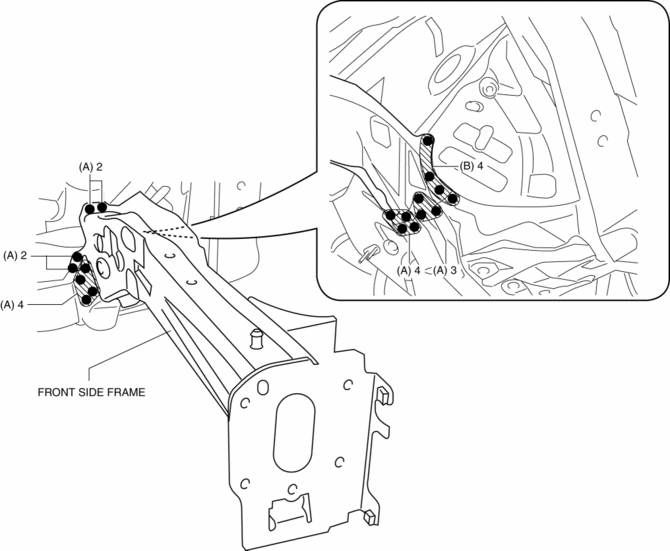
3. Remove the front side frame.
 Front Side Frame Installation [Panel Replacement]
Symbol Mark
Installation Procedure
1. When installing new parts, measure and adjust the body as necessary to conform
with standard dimensions.
2. Drill holes for the plug welding before inst ...
 Rear Body Straight Line Dimensions (1) [Dimensions]
Point symbol
Designation
Hole diameter or bolt or nut size mm {in}
A
Liftgate hinge installation hole
?12 {0 ...
Other materials:
Active Command Modes Inspection [Blind Spot Monitoring (Bsm)]
1. Connect the M-MDS to the DLC-2.
2. After the vehicle is identified, select the following items from the initialization
screen of the M-MDS.
a. Select “DataLogger”.
b. Select “Modules”.
c. Select “BSML” or “BSMR”.
3. Select the simulation items from the PID table.
4. ...
Passenger Compartment Temperature Sensor Removal/Installation [Full Auto Air
Conditioner]
1. Disconnect the negative battery cable..
2. Remove the following parts:
a. Front scuff plate (driver-side).
b. Front side trim (driver-side).
c. Switch panel.
d. Decoration panel.
e. Shift lever knob (MTX).
f. Front console box.
g. Shift panel.
h. Upper panel.
i. Rear console. ...
Charging System [Skyactiv G 2.0]
Outline
Regulator-less generator (built-in power transistor) has been adopted.
A generator using two delta connection type stator coils has been adopted.
Structural View
Structure
Consists of the following parts:
Battery
(See B ...
