Mazda CX-5 Service & Repair Manual: Front Frame (Rear) Installation [Panel Replacement]
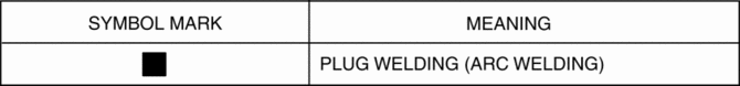
Symbol Mark
Installation Procedure
1. When installing new parts, measure and adjust the body as necessary to conform with standard dimensions.
2. Drill holes for the plug welding before installing the new parts.
3. After temporarily installing new parts, make sure the related parts fit properly.
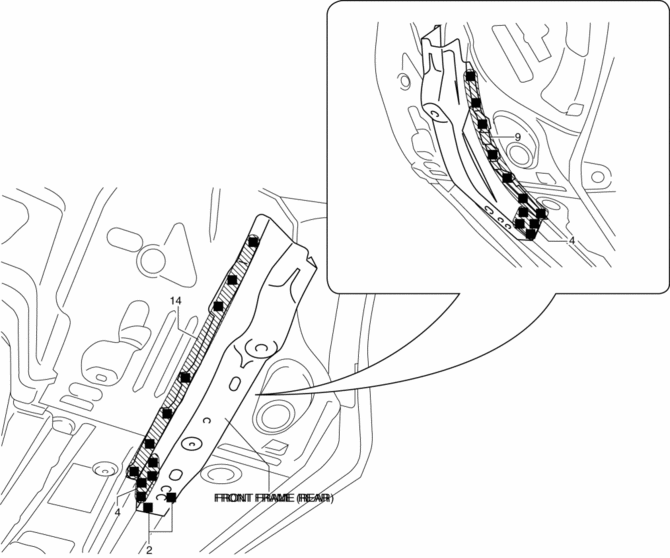
4. Plug weld the 33 locations shown in the figure, then install the front frame (rear).
 Front Crossmember Removal/Installation
CAUTION:
Performing the following procedures without first removing the front ABS
wheel-speed sensor may possibly cause an open circuit in the wiring harness
if it is pulled by mistake. ...
 Front Frame (Rear) Removal [Panel Replacement]
Symbol Mark
Removal Procedure
1. Drill the 33 locations shown in the figure.
NOTE:
When drilling, do not drill a hole all the way through or there could be
a problem when installing ...
Other materials:
Transaxle Fluid Temperature (Tft) Sensor [Fw6 A EL, Fw6 Ax EL]
Purpose/Function
The transaxle fluid temperature (TFT) sensor detects the ATF temperature
in the oil pan.
The transaxle fluid temperature (TFT) sensor signal is used for automatic
shift control, TCC control, line pressure control, direct electric shift control,
learning contr ...
Rear Upper Arm Removal/Installation [Awd]
WARNING:
Verify that the crossmember is securely supported by a jack. If the rear
crossmember falls off, it can cause serious injury or death, and damage to the
vehicle.
CAUTION:
Performing the following procedures without first removing the rear ABS wheel-speed
sensor ...
Lap Pre Tensioner Seat Belt [Two Step Deployment Control System]
Purpose
The lap pre-tensioner seat belts retract and tighten the seat belt webbing
to protect the front passengers during a collision.
Function
The lap pre-tensioner seat belts operate (deploy) based on the operation
signal from the SAS control module to instantly retract a ...
