Mazda CX-5 Service & Repair Manual: Front Console Removal/Installation
CAUTION:
-
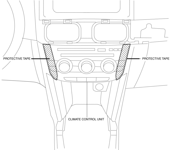
Affix protective tape to the position shown in the figure.

1. Disconnect the negative battery cable..
2. Remove the following parts:
a. Decoration panel.
b. Shift lever knob (MTX).
c. Front console box.
d. Shift panel.
e. Upper panel.
f. Rear console.
g. Side wall.
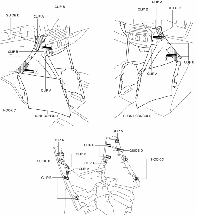
3. Take the shaded area shown in the figure, and remove the front console in the direction of the arrow in the order of (1), (2), (3), (4) while detaching clips A, clips B, hooks C, guides D.

4. Disconnect the front accessory socket connector.
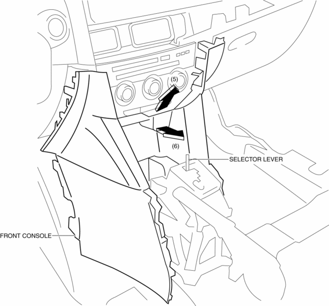
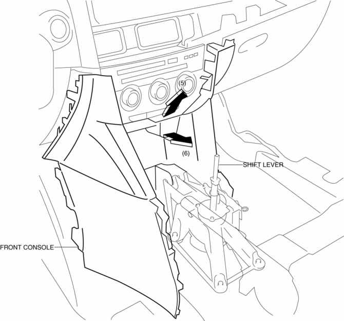
5. Pull the front console in the direction of the arrow in the order of (5), (6) and remove the front console while detaching the selector lever (ATX) or shift lever (MTX).
ATX

MTX

6. Install in the reverse order of removal.
 Front Console Box Removal/Installation
NOTE:
Affix protective tape to the position shown in the figure.
1. Insert a tape-wrapped flathead screwdriver in the position indicated by the
arrow in the figure and detach cl ...
 Glove Compartment Removal/Installation
1. Push the glove compartment in the direction of the arrow (1) and remove hooks
A.
2. Pull the stay damper in the direction of the arrow (2) shown in the figure
and remove the hook B.
CAU ...
Other materials:
Rear Drive Shaft Disassembly/Assembly
1. Disassemble in the order indicated in the table.
2. Assemble in the reverse order of disassembly.
1
Boot band (differential side)
(See Boot Band (Differential Side) Disassembly Note.)
(See Boot Band (Differential Side) Assembly Note.)
2
...
Seat Belt Warning Light
Purpose
The seat belt warning light warns the driver that a seat belt is not fastened.
Function
The instrument cluster flashes/illuminates the seat belt warning light based
on the following CAN signals:
Vehicle speed signal sent from PCM
Driver/passenge ...
Clock Spring Inspection [Two Step Deployment Control System]
1. Disconnect the negative battery cable and wait for 1 min or more..
2. Remove the driver?side air bag module..
3. Remove the steering wheel..
4. Remove the column cover..
5. Remove the clock spring..
6. Verify that the continuity is as indicated in the table.
If not as indicated ...
