Mazda CX-5 Service & Repair Manual: Cowl Upper Plate Installation [Panel Replacement]
Symbol Mark

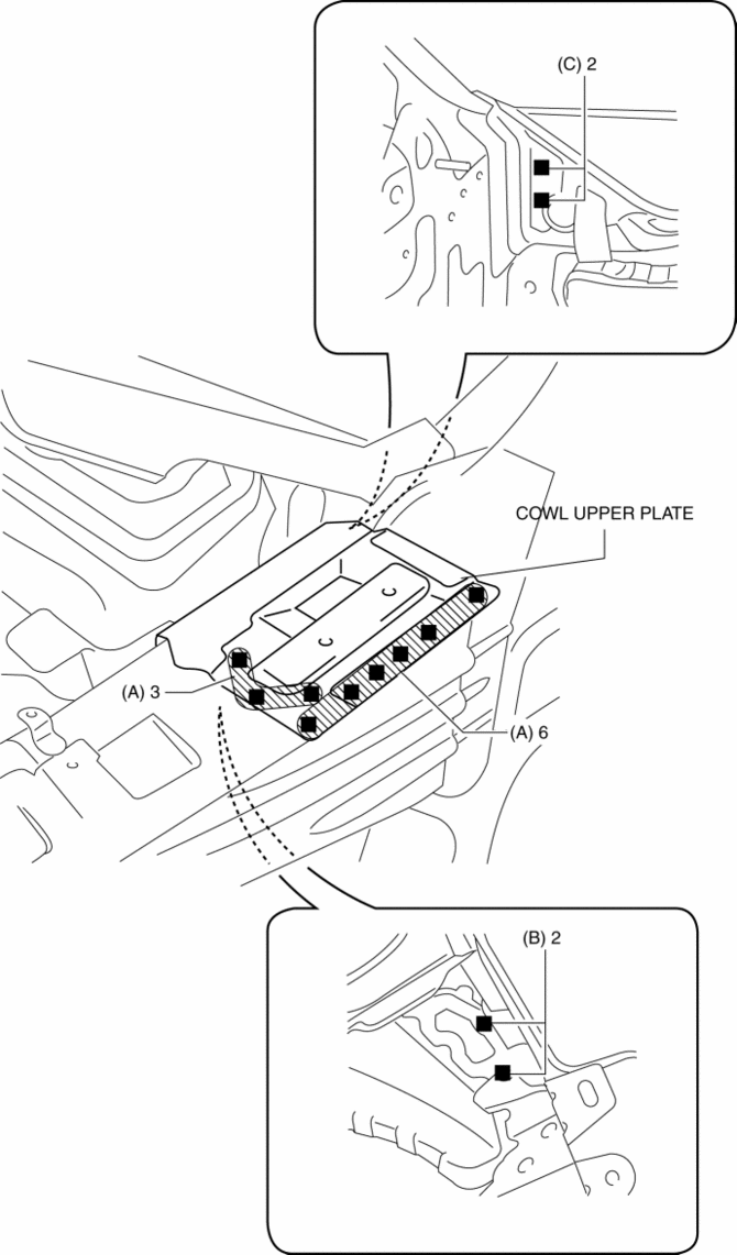
Installation Procedure
1. When installing new parts, measure and adjust the body as necessary to conform with standard dimensions.
2. Drill holes for the plug welding before installing the new parts.
3. After temporarily installing new parts, make sure the related parts fit properly.
4. Plug weld the 9 locations indicated by (A) shown in the figure.
5. Plug weld the 2 locations indicated by (B) from the front wheel housing side shown in the figure.
6. Plug weld the 2 locations indicated by (C) from the inside shown in the figure, then install the cowl upper plate.
 Cowl Panel Removal/Installation
1. Disconnect the negative battery cable..
2. Remove the following parts:
a. Windshield wiper arm and blade.
b. Cowl grille.
c. Windshield wiper motor.
d. Keyless beeper.
3. Remove clips A ...
 Cowl Upper Plate Removal [Panel Replacement]
Symbol Mark
Removal Procedure
1. Drill the 9 locations indicated by (A) shown in the figure.
2. Drill the 2 locations by (B) from the front wheel housing side shown in the
figure.
3. Drill ...
Other materials:
Magnet Clutch [Manual Air Conditioner]
Purpose
The magnetic clutch transmits the rotation force from the engine to the shaft
in the A/C compressor.
Function
The magnetic clutch engages or disengages the magnetic clutch and the A/C
turns on or off by switching the power transmission from the engine.
Con ...
Charging System [Skyactiv G 2.0]
Outline
Regulator-less generator (built-in power transistor) has been adopted.
A generator using two delta connection type stator coils has been adopted.
Structural View
Structure
Consists of the following parts:
Battery
(See B ...
Shift Lock System [Fw6 A EL, Fw6 Ax EL]
Purpose, Function
The shift-lock system operates when the ignition is switched to ON and the
brake pedal is not depressed, and inhibits the selector lever from being shifted
from the P position to other positions.
If the shift-lock cannot be released by the normal operation, it ...
