Mazda CX-5 Service & Repair Manual: Bumper Bracket Installation [Panel Replacement]
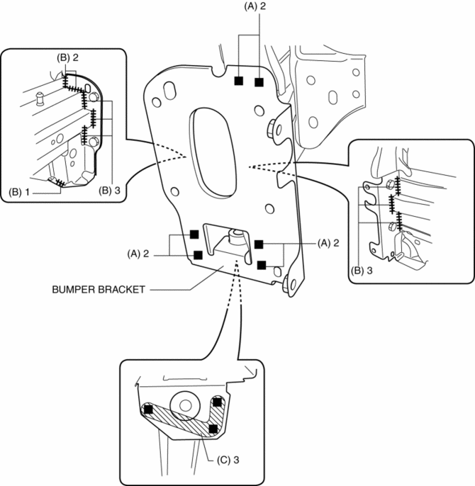
Symbol Mark

Installation Procedure
1. When installing new parts, measure and adjust the body as necessary to conform with standard dimensions.
2. Drill holes for the plug welding 6 locations indicated by (A) and 3 locations indicated by (C) shown in the figure, before installing the new parts.
3. After temporarily installing new parts, make sure the related parts fit properly.
4. Plug weld the 6 locations indicated by (A) shown in the figure.

5. Continuos weld the 9 locations indicated by (B) shown in the figure from the front wheel housing and engine room.
NOTE:
-
A flange part is fixed by a hand vise, and where a welded area is press-fitted, welding is performed so that a clearance does not open in the part welded.
6. Plug weld the 3 locations indicated by (C) shown in the figure, then install the bumper bracket.
 Body Panel
Outline
The multi-load path and triple H-shaped structure of distributing the power
absorbed at the collision were used for the body shell.
A ring structure has been adopted for the ...
 Bumper Bracket Removal [Panel Replacement]
Symbol Mark
Removal Procedure
1. Rough cut area locations indicated by (A).
2. Grind the 6 locations indicated by (B) shown in the figure.
CAUTION:
When grinding 6 locations indi ...
Other materials:
Automatic Transaxle Removal/Installation [Fw6 Ax EL]
CAUTION:
Performing the following procedures without first removing the front ABS
wheel-speed sensor may possibly cause an open circuit in the harness if it is
pulled by mistake. Before performing the following procedures, disconnect the
front ABS wheel-speed sensor (axle side) and ...
Canister Vent (Cv) Solenoid Valve Removal/Installation
U.S.A. And CANADA
1. Disconnect the negative battery cable..
2. Remove the floor under cover (LH)..
3. Disconnect the evaporative hose No.2..
4. Remove in the order indicated in the table.
1
CV solenoid valve connector
2
CV solenoid va ...
Clutch Pedal Position Switch Removal/Installation [C66 M R]
1. Disconnect the negative battery cable..
2. Disconnect the clutch pedal position switch connector.
3. Rotate the clutch pedal position switch 45° counterclockwise.
4. Remove the clutch pedal position switch from the clutch pedal.
5. Insert a new clutch pedal position switch into t ...
