Mazda CX-5 Service & Repair Manual: After Service Precaution
WARNING:
-
Fuel line spills and leakage are dangerous. Fuel can ignite and cause serious injuries or death and damage. When installing the fuel hose, perform “Fuel Leakage Inspection” described below.
-
A person charged with static electricity could cause a fire or explosion, resulting in death or serious injury. Before performing work on the fuel system, discharge static electricity by touching the vehicle body.
Fuel Leakage Inspection
Using M-MDS
1. Connect the M-MDS to the DLC-2.
2. Switch the ignition to ON (engine off).
3. Using the simulation function “FP”, start the fuel pump..
4. Verify that there is no fuel leakage from the pressurized parts.
-
Standard
-
There shall be no leakage after 5 min.
5. In the case of fuel leakage, replace the following components and then recheck using the fuel leakage checking procedure.
-
If there is leakage, replace the fuel hoses and clips.
-
If there is damage on the seal on the fuel pipe side, replace the fuel pipe.
Without using M-MDS
1. Disconnect the negative battery cable..
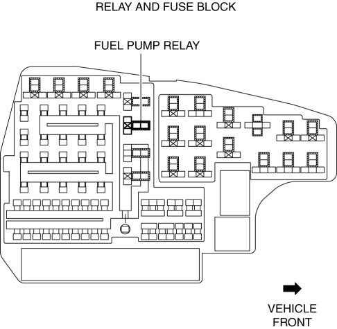
2. Remove the fuel pump relay.

CAUTION:
-
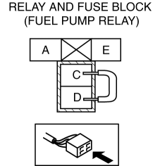
Short the specified terminals because shorting the wrong terminal of the relay and fuse block may cause malfunctions.
3. Using a jumper wire, short fuel pump relay terminals C and D in the relay and fuse block.

4. Connect the negative battery cable and operate the fuel pump..
5. Verify that there is no fuel leakage from the pressurized parts.
-
Standard
-
There shall be no leakage after 5 min.
6. In the case of fuel leakage, replace the following components and then recheck using the fuel leakage checking procedure.
-
If there is leakage, replace the fuel hoses and clips.
-
If there is damage on the seal on the fuel pipe side, replace the fuel pipe.
 Fuel
Fuel
...
 Before Service Precaution
WARNING:
Fuel vapor is hazardous. It can very easily ignite, causing serious injury
and damage. Always keep sparks and flames away from fuel.
Fuel line spills and leakage from the p ...
Other materials:
Air Bag System Warning Alarm [Standard Deployment Control System]
Purpose
The air bag system warning alarm notifies the driver that a malfunction occurred
in the air bag system instead of the air bag system warning light.
Function
If a malfunction occurs in the air bag system while the air bag system warning
light cannot illuminate, the a ...
Power Flow [Fw6 A EL, Fw6 Ax EL]
Power flow
1 GR
2 GR
3 GR
4 GR
5 GR
6 GR
REVERSE
...
Slide Motor Removal/Installation
WARNING:
Handling a side air bag improperly can accidentally operate (deploy) the
air bag, which may seriously injure you. Read the service warnings/cautions
in the Workshop Manual before handling the front seat (side air bag integrated)..
If the sliding mechanisms on both side ...
