Mazda CX-5 Service & Repair Manual: Headlight Aiming
NOTE:
-
Perform headlight aiming if any of the following work is performed.
-
Front combination light replacement
-
Work that can affect vehicle height such as suspension replacement or removal/installation.
1. Empty the vehicle by having all occupants leave the vehicle and remove all the cargo except for the spare tire, jack and tools equipped on the vehicle.
2. Adjust the air pressure of each tire to the specified value..
3. Move the vehicle to level ground.
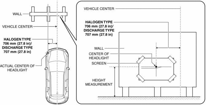
4. Make a screen shown in the figure using double-weight, white paper.
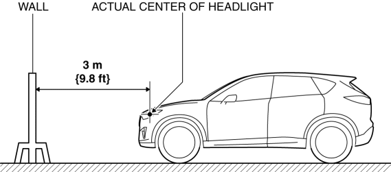
5. Line up the vehicle with the wall so that the distance to the headlights is 3 m {9.8 ft}
from the wall.
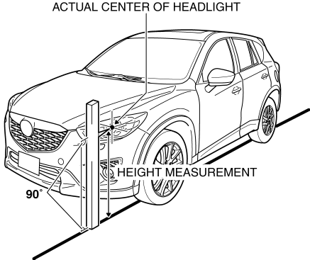
6. Measure the height at the center point of the headlight.
NOTE:
-
Measure the height at the center point of the headlight in which the aiming is being adjusted because the vehicle height differs depending on vehicle conditions.
7. Align the center of the headlight with the center of the screen.
8. Set a partition in front of the headlight which is not being adjusted to block the light.
9. Start the engine and charge the battery.
10. Turn on the headlight low beams.
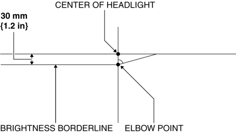
11. Verify that the elbow point of the headlight is at the position indicated on the adjustment screen.
-
If the elbow point of the headlight is not at the position indicated on the adjustment screen, perform the following adjustment.
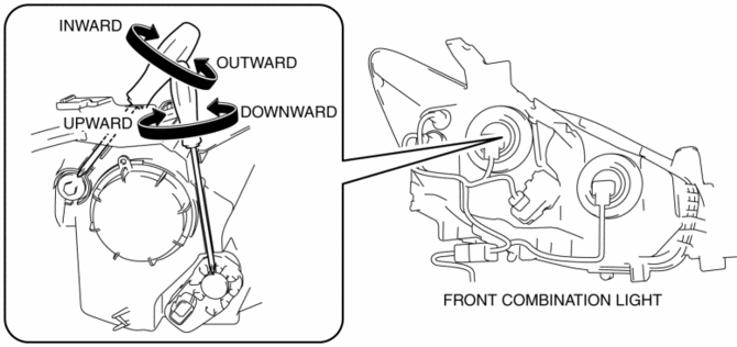
a. Rotate the adjustment screw to adjust the headlight.
 Front Fog Lights Indicator Light
Purpose
Notifies the user that the front fog lights are illuminated.
Function
Illuminates when the front fog light illumination conditions are met.
Construction
Displa ...
 Headlight Auto Leveling System
Outline
Automatically adjusts the headlight optical axis in response to changes in
load and passenger conditions to prevent blinding of oncoming vehicles from
headlight glare and to assur ...
Other materials:
Pre Delivery Inspection
Pre?Delivery Inspection Table
Exterior
INSPECT and ADJUST, if necessary, the following items to specification:
?Glass, exterior bright metal and paint for damage
?Wheel lug nuts
?All weatherstrips for damage or detachment
?Adjust tire pressures to specification
Adjust the tire pr ...
Rear Bumper Disassembly/Assembly
1. Disassemble in the order indicated in the table.
1
Screw
2
Reflector
3
Rear bumper face
2. Assemble in the reverse order of disassembly. ...
Front Seat Back Component Removal/Installation
WARNING:
Handling a side air bag improperly can accidentally operate (deploy) the
air bag, which may seriously injure you. Read the service warnings/cautions
in the Workshop Manual before handling the front seat (side air bag integrated)..
If the sliding mechanisms on both side ...
