Mazda CX-5 Service & Repair Manual: Side Turn Light
Purpose
-
The side turn lights are used to signal vehicles/people at the side of the vehicle that the vehicle is going to make a right or left turn.
Function
-
The side turn lights flash according to the operation of the turn or the hazard switch.
Construction
-
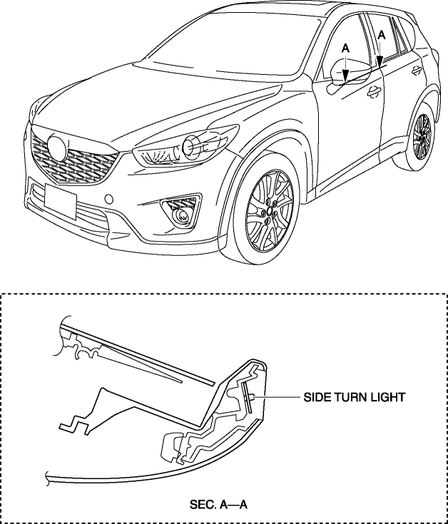
Side turn lights built into the outer mirrors have been adopted.
-
LED type side turn lights have been adopted.

Operation
Turn system
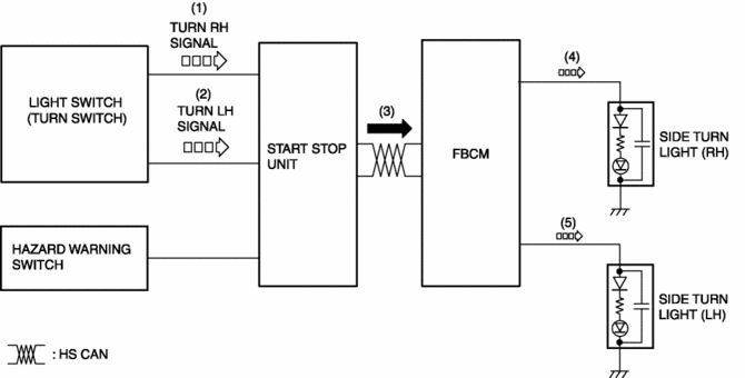
1. When the turn switch is operated to the RH position, a turn RH signal is input to the start stop unit.
2. When the turn switch is operated to the LH position, a turn LH signal is input to the start stop unit.
3. The start stop unit sends the turn RH or LH signal to the front body control module (FBCM).
4. When the front body control module (FBCM) receives the turn RH signal, the side turn light (RH) flashes.
5. When the front body control module (FBCM) receives the turn LH signal, the side turn light (LH) flashes.

Hazard system
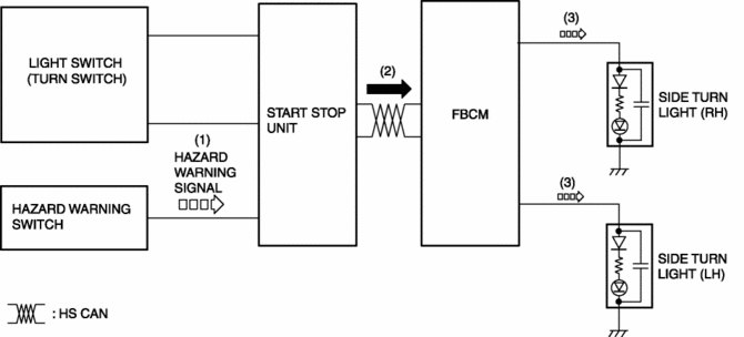
1. When the hazard switch is turned on, a hazard signal is input to the start stop unit.
2. The start stop unit sends a hazard signal to the front body control module (FBCM).
3. When the front body control module (FBCM) receives the hazard signal, the side turn lights (RH) and (LH) flash.

Fail-safe
-
Function not equipped.
 Rear Turn Light Bulb Removal/Installation
1. Disconnect the negative battery cable..
2. Insert a tape-wrapped flathead screwdriver into the service hole in the position
shown in the figure.
3. Move the flathead screwdriver in the di ...
 Side Turn Light Inspection
1. Disconnect the negative battery cable..
2. Remove the following parts:
a. Outer mirror glass.
b. Upper outer mirror garnish.
c. Side turn light.
3. Apply battery voltage to side turn ligh ...
Other materials:
Cruise Main Indicator Light (Amber)
Purpose/Function
Illuminates while the cruise control system is in standby mode to inform
the driver that the cruise control system is on standby.
Construction
Built into the instrument cluster.
Operation
Illuminates while the cruise control system is on sta ...
Rear Door Hinge Removal/Installation
1. Disconnect the negative battery cable..
2. Remove the following parts:
a. Rear door.
b. Front scuff plate.
c. Rear scuff plate.
d. B-pillar lower trim.
3. Remove in the order shown in the figure.
1
Bolt
2
Nut
3 ...
Floor Side Panel Installation [Panel Replacement]
Symbol Mark
Installation Procedure
1. When installing new parts, measure and adjust the body as necessary to conform
with standard dimensions.
2. Drill holes for the plug welding before installing the new parts.
3. After temporarily installing new parts, make sure the related parts fit p ...
