
Mazda CX-5 Service & Repair Manual: Rear Scuff Plate Removal/Installation
1. Take the shaded area shown in the figure, detach tab A while pulling the rear scuff plate in the direction of the arrow (1) shown in the figure, then detach hook B, clips C, pins D while pulling in the direction of the arrow (2).
2. Take the shaded area shown in the figure, detach tab E while pulling the rear scuff plate in the direction of the arrow (3) shown in the figure, then detach the hook F while pulling in the direction of the arrow (4).
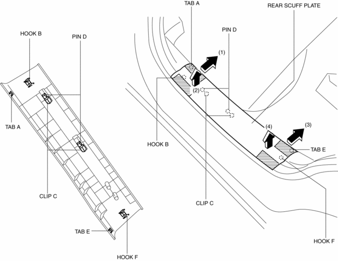
3. Install in the reverse order of removal.
 Procedure [Plastic Body Parts]
Repair of polypropylene bumpers having damage that has reached the surface of
the polypropylene and are too serious to be restored by painting only.
1. Cut the rough edges around the damage wit ...
 Repairable Range Of Polypropylene Bumpers [Plastic Body Parts]
The three types of damaged bumpers shown below are considered repairable. Although
a bumper which has been damaged greater than this could also be repaired, it should
be replaced with a new one be ...
Other materials:
Crankshaft Position (CKP) Sensor Removal/Installation
CAUTION:
When foreign material such as an iron chip is on the CKP sensor, it can cause
abnormal output from the sensor because of flux turbulence and adversely affect
the engine control. Be sure there is no foreign material on the CKP sensor when
replacing.
Do not assemble t ...
Rear Parking Brake Cable Removal/Installation
1. Remove the front console box..
2. Remove the shift lever knob. (MTX).
3. Remove the shift panel..
4. Remove the upper panel..
5. Remove the rear console..
6. Loosen the adjusting nut.
7. Remove the floor under cover No.2..
8. Remove in the order indicated in the table.
9. Install ...
Front Seat Cushion Frame Removal/Installation
WARNING:
Handling a side air bag improperly can accidentally operate (deploy) the
air bag, which may seriously injure you. Read the service warnings/cautions
in the Workshop Manual before handling the front seat (side air bag integrated)..
If the sliding mechanisms on both side ...
