
Mazda CX-5 Service & Repair Manual: Rear Lateral Link Removal/Installation
1. Disconnect the rear stabilizer control link lower side nut..
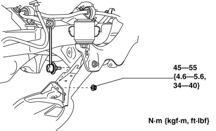
2. Remove in the order indicated in the table.
3. Install in the reverse order of removal.
4. Inspect the wheel alignment and adjust it if necessary..
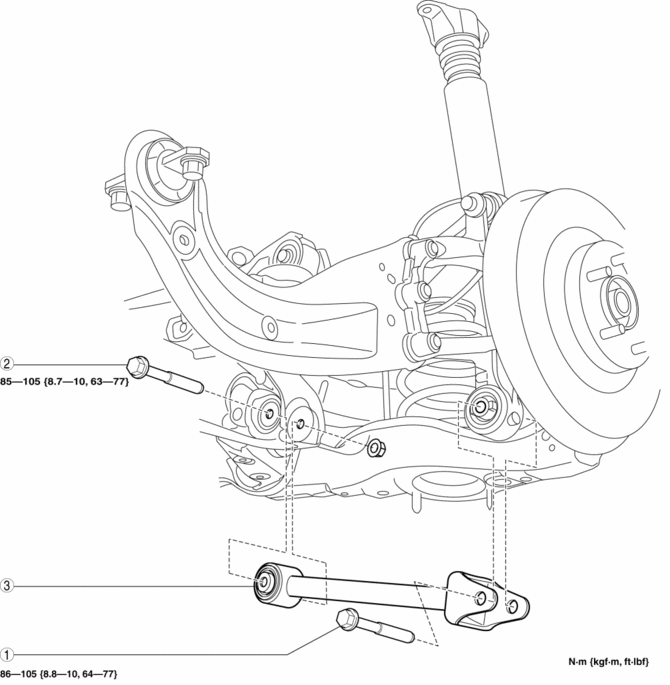
|
1 |
Rear lateral link outer bolt |
|
2 |
Rear lateral link inner bolt |
|
3 |
Rear lateral link (See Rear Lateral Link Removal Note.) (See Rear Lateral Link Installation Note.) |
Rear Lateral Link Removal Note
1. Jack up the vehicle to the unloaded condition, and support the axle component using a jack.
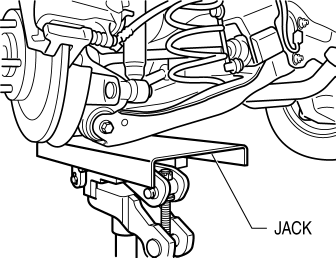
2. Remove the rear lateral link.
Rear Lateral Link Installation Note
1. Jack up the vehicle to the unloaded condition, and support the axle component using a jack.
2. Install the rear lateral link.
 Rear Drive Shaft Removal/Installation
CAUTION:
Performing the following procedures without first removing the ABS wheel?speed
sensor may possibly cause an open circuit in the harness if it is pulled by
mistake. Before perf ...
 Rear Lower Arm Removal/Installation
WARNING:
Be careful not to allow the coil spring to fly off when removing/installing
the coil spring. Otherwise, the coil spring could fly off and cause serious
injury or death, or dam ...
Other materials:
Precaution [Dynamic Stability Control (DSC)]
1. The ABS warning light and/or brake system warning light and/or TCS/DSC indicator
light and/or TCS OFF indicator light illuminate even when the system is normal.
Warning lights/Indicator lights that may illuminate and/or flash
Cases in which the light may ill ...
Timing Chain, Chain Tensioner
Purpose, Function
Timing chain
The timing chain transmits the rotation force of the crankshaft to the camshaft
to perform the rotation timing of the crankshaft and camshaft.
Chain tensioner
The chain tensioner constantly maintains the timing chain tension and the
timing ch ...
Front Seat Cushion Frame Removal/Installation
WARNING:
Handling a side air bag improperly can accidentally operate (deploy) the
air bag, which may seriously injure you. Read the service warnings/cautions
in the Workshop Manual before handling the front seat (side air bag integrated)..
If the sliding mechanisms on both side ...
