Mazda CX-5 Service & Repair Manual: Hill Launch Assist (Hla)
Purpose/Function
-
The hill launch assist (HLA) is a function which assists the driver in accelerating the vehicle on a slope by activating the traction control solenoid valve in the DSC HU/CM when the vehicle begins accelerating on a slope, and maintaining/reducing brake fluid pressure to prevent the vehicle from rolling for a specified time.
-
The system automatically operates when the vehicle is stopped on a slope of approx. 3 % or more (changes slightly depending on load and vehicle conditions such as tire wear and air pressure). (MTX)
-
The system automatically operates when the vehicle is stopped on a slope of approx. 6 % or more (changes slightly depending on load and vehicle conditions such as tire wear and air pressure). (ATX)
NOTE:
-
The shift lever position is in the other than R position, the hill launch assist (HLA) operates on a upslope. (MTX)
-
The selector lever position is in the D/M position, the hill launch assist (HLA) operates on a upslope. (ATX)
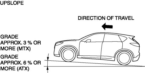
-
The selector/shift lever position is in the R position, the hill launch assist (HLA) operates on a downslope.
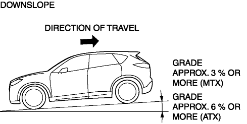
-
The hill launch assist (HLA) operates constantly without affecting the TCS OFF switch operation.
-
When the parking brake is applied, the hill launch assist (HLA) does not operate.
-
When the DSC indicator light illuminates, the hill launch assist (HLA) does not operate.
-
Structure
-
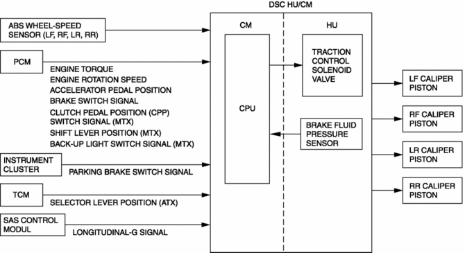
The hill launch assist (HLA) constantly controls the brake fluid pressure in accelerating the vehicle on a slope by determining the hill launch assist (HLA) operation based on the signals input from each module via CAN communication, wheel speed signals from the ABS wheel-speed sensor.
Block diagram
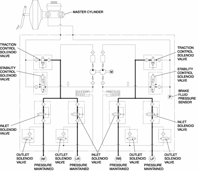
Hydraulic circuit diagram
Operation
-
If all of the following conditions are met while the vehicle is stopped on a slope, the DSC HU/CM performs controls to maintain brake fluid pressure (control the linear control solenoid valve) even if the driver has released the brake pedal.
Hold control
-
Control conditions (all of the following conditions met):
-
Engine speed is at a certain value or more
-
All doors are fully closed
-
Slope of approx. 3 % or more (MTX)
-
Slope of approx. 6 % or more (ATX)
-
Wheel speed is 0 km/h {0 mph}
-
Parking brake not operated
-
Accelerator pedal not depressed
-
Not fail-safe mode is present
-
Upslope: The selector lever position is in the D/M position (ATX)
-
Upslope: The shift lever position is in the position other than R (MTX)
-
Downslope: The selector/shift lever position is in the R position
-
Brake pedal is depressed and brake fluid pressure is at a certain value or more
-
Clutch pedal depressed (MTX)
-
Control description
-
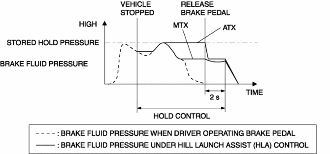
If all of the control conditions are met, the DSC HU/CM controls the traction control solenoid valve and maintains brake fluid pressure (driver can depress brake pedal more at this time).
-
If the brake pedal is released, brake fluid pressure (hold-pressure stored in memory) is maintained for a maximum of 2 s.
Release control
-
Control condition
-
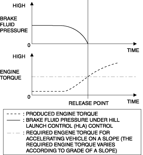
After the accelerator pedal is depressed, the required engine torque for accelerating vehicle on a slope is produced
-
Control description
-
Brake fluid pressure being maintained is lowered depending on produced engine torque.
Slow release control
-
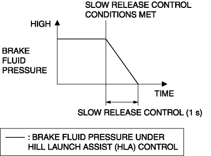
Control condition (one or more of following conditions are met):
-
Parking brake applied
-
Clutch pedal released (MTX)
-
DSC HU/CM has malfunction (performs slow release control only if solenoid valve control is available)
-
0.2 s has elapsed on slope of 1.0 % or less
-
2 s have elapsed with brake pedal released
-
Control description
-
Brake fluid pressure being maintained is lowered in 1 s
Fast release control
-
Control condition
-
DSC HU/CM has malfunction and solenoid valve control is not available
-
Control description
-
Brake fluid pressure being maintained is reduced to 0 kPa {0 mmHg, 0 inHg} immediately
 Ebd Control
Outline
EBD control uses the ABS system to control brake fluid pressure distribution
to the rear wheels so that they do not lock-up prior to the front wheels during
braking, thereby preve ...
 Precaution [Dynamic Stability Control (DSC)]
1. The ABS warning light and/or brake system warning light and/or TCS/DSC indicator
light and/or TCS OFF indicator light illuminate even when the system is normal.
Warning ...
Other materials:
Air Bag System Service Cautions [Two Step Deployment Control System]
Air Bag System Component Disassembly
Disassembling the air bag system components could cause it to not operate
(deploy) normally. Never disassemble any air bag system components.
Air Bag Module, Pre-tensioner Seat Belt, Lap Pre-tensioner Seat Belt Handling
Oil, grease, or ...
Pre Tensioner Seat Belt [Standard Deployment Control System]
Purpose
The pre-tensioner seat belt retracts and tightens the seat belt webbing to
protect the front passengers during a collision.
Function
The pre-tensioner seat belts operate (deploy) based on the operation signal
from the SAS control module to instantly retract and tigh ...
Precaution [Dynamic Stability Control (DSC)]
1. The ABS warning light and/or brake system warning light and/or TCS/DSC indicator
light and/or TCS OFF indicator light illuminate even when the system is normal.
Warning lights/Indicator lights that may illuminate and/or flash
Cases in which the light may ill ...
