Mazda CX-5 Service & Repair Manual: Front Scuff Plate Removal/Installation
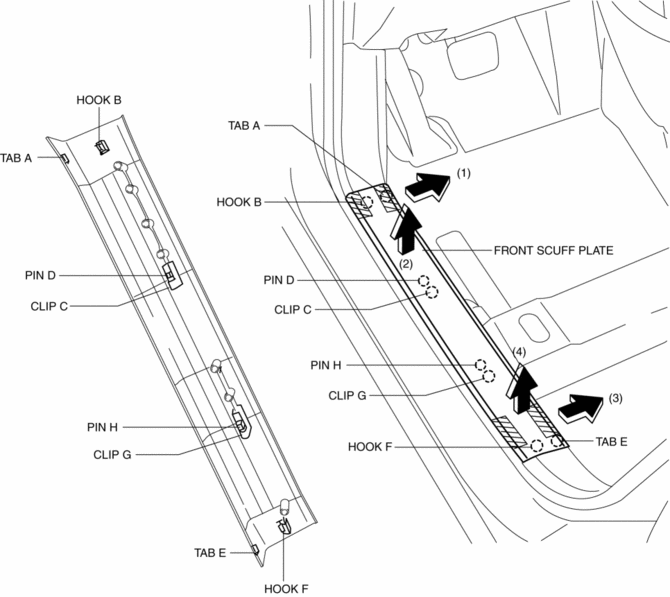
1. Take the shaded area shown in the figure, detach tab A while pulling the front scuff plate in the direction of the arrow (1) shown in the figure, then detach the hook B, clip C, and pin D while pulling in the direction of the arrow (2).
2. Take the shaded area shown in the figure, detach tab E while pulling the front scuff plate in the direction of the arrow (3) shown in the figure, then detach the hook F, clip G and pin H while pulling in the direction of the arrow (4).
3. Install in the reverse order of removal.
 Floor Insulator Removal/Installation
Driver-side
1. Disconnect the negative battery cable..
2. Remove the following parts:
a. Driver-side front scuff plate.
b. Driver-side front side trim.
c. Decoration panel.
d. Shift lever k ...
 Front Side Trim Removal/Installation
1. Remove the front scuff plate..
2. Partially peel back the seaming welt.
3. Remove the cap nut.
4. Pull the front side trim in the direction of the arrow shown in the figure
and remove i ...
Other materials:
Rear Differential Disassembly
WARNING:
The engine stand is equipped with a self-lock mechanism, however, if the
rear differential is in a tilted condition, the self-lock mechanism could become
inoperative. If the rear differential unexpectedly rotates it could cause injury,
therefore do not maintain the rear dif ...
Differential Oil Temperature Sensor Inspection
WARNING:
Hot differential oil may cause severe burns. Do not perform maintenance while
differential oil is hot.
1. Disconnect the negative battery cable.
2. Disconnect the differential oil temperature sensor connector and remove the
differential oil temperature sensor.
3. Wrap ...
Front Combination Light
Purpose
Parts related to the front exterior lights are grouped and housed together
such as the headlight, front turn/parking light, headlight leveling actuator,
wiring harnesses, and connectors.
Function
Each light illuminates or flashes when the light switch, turn switch, ...
