
Mazda CX-5 Service & Repair Manual: Condenser Removal/Installation
1. Disconnect the negative battery cable..
2. Discharge the refrigerant..
3. Remove the front under cover No.1..
4. Drain the engine coolant..
5. Remove the following parts:
a. Plug hole plate.
b. Air cleaner, air hose and fresh air duct component.
c. Coolant reserve tank.
d. Cooling fan component.
e. Radiator.
6. Remove the bolts.
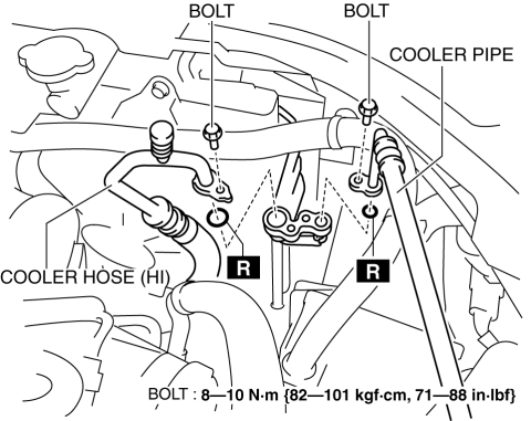
7. Disconnect the cooler hose (HI) and cooler pipe. Do not allow remaining compressor oil in the refrigerant line to spill..
CAUTION:
-
If moisture or foreign material enters the refrigeration cycle, cooling ability will be lowered and abnormal noise or other malfunction could occur. Always plug open fittings immediately after removing any refrigeration cycle parts.
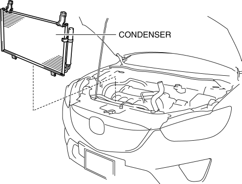
8. Remove the condenser, being careful not to allow remaining compressor oil in the condenser to spill..
CAUTION:
-
If moisture or foreign material enters the refrigeration cycle, cooling ability will be lowered and abnormal noise or other malfunction could occur. Always plug open fittings immediately after removing any refrigeration cycle parts.
9. Install in the reverse order of removal.
10. Inspect for engine coolant leakage..
11. Perform the refrigerant system performance test..
Condenser Installation Note
1. After replacing the condenser, add compressor oil to the refrigeration cycle.
-
Supplemental oil amount (approx. quantity)
-
13 ml {13 cc, 0.44 fl oz}
 Condenser Inspection
1. Inspect the condenser for cracks, damage, and oil leakage.
If there is any malfunction, replace the condenser.
2. Visually inspect for bent fins for clogging of foreign material.
...
 Condenser Removal/Installation
1. Disconnect the negative battery cable..
2. Remove the following parts:
a. Trunk board.
b. Trunk end trim (LH).
c. Rear scuff plate (LH).
d. Trunk side trim (LH).
e. D-pillar trim (LH). ...
Other materials:
Climate Control Unit Removal/Installation [Full Auto Air Conditioner]
NOTE:
The climate control unit prior to replacement stores the vehicle specification
information.
The new climate control unit does not store any vehicle specification information.
When the ignition is switched ON after the climate control unit is replaced,
the climate ...
Camshaft Position (CMP) Sensor
Purpose/Function
Detects the camshaft speed as basic information for mainly determining the
fuel injection timing and ignition timing.
Detects the camshaft speed and inputs it to the PCM as a CMP signal.
Construction
Intake CMP sensor
Installed on the cylinder head.
...
Charcoal Canister
Purpose, Function
Absorbs evaporative gas flowing from the fuel tank to prevent release of
the gas into the atmosphere.
Construction
The charcoal canister is installed near the fuel tank.
U.S.A. and CANADA
Except U.S.A. and CANADA
The charcoal canister ...
