
Mazda CX-5 Service & Repair Manual: Car Navigation Unit Removal/Installation
CAUTION:
-
The audio unit communicates with the car-navigation unit and records the presence/non-presence of the car-navigation unit when the ignition is switched to ACC or ON (engine off or on) after connecting the negative battery cable.
-
If the commander switch is installed with the negative battery cable connected when the audio unit records that there is no car-navigation unit, the car-navigation unit does not operate.
-
For the car-navigation unit installation/removal, disconnect the negative battery cable, switch the ignition to ACC or ON (engine off or on) after the servicing is completed, and the audio unit records the presence/non-presence of the car-navigation unit.
1. Disconnect the negative battery cable..
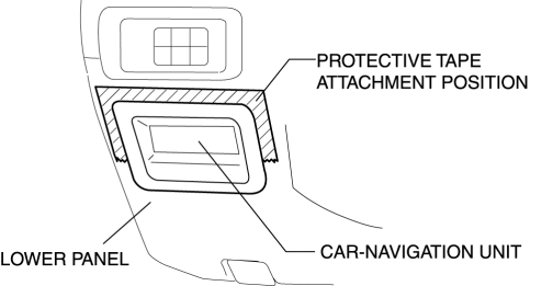
2. Affix protective tape to the gaps between the car-navigation and lower panel as shown in the figure.
CAUTION:
-
Before inserting a flathead screwdriver into the gap between the car-navigation and lower panel, affix protective tape to prevent damage. Otherwise, the lower panel could be damaged by the flathead screwdriver.
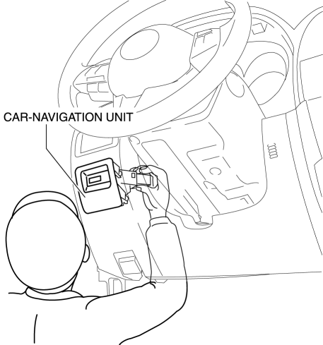
3. Insert your hand from the lower side of the lower panel and press the car-navigation unit so that there is a gap on the upper side of the car-navigation unit.
4. Insert a tape-wrapped fastener remover into the gap between the lower panel and car-navigation unit.
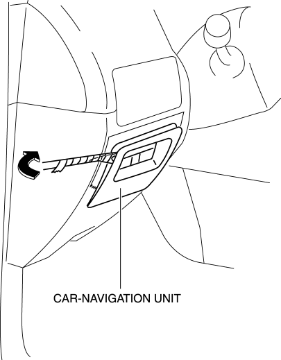
5. Move the fastener remover to the position of the arrow shown in the figure and detach the car-navigation unit clip from the lower panel.
6. Pull out the car-navigation unit and disconnect the connectors.
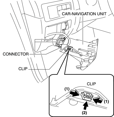
7. While pressing the tabs of the clip in the direction of arrows (1) shown in the figure, press the clip in the direction of arrow (2) to detach it from the car-navigation unit.
8. Remove the clip.
9. Remove the car-navigation unit.
10. Install in the reverse order of removal..
Installation Note
-
Pressing the car-navigation unit when installing it could result in a malfunction. Therefore, press the panel area to install the car-navigation unit.
 Car Navigation Unit
Purpose
Reads the SD card data inserted into the car-navigation unit and sends the
read data to the audio unit.
Function
The car-navigation unit has the following functions:
...
 Global Positioning System (Gps) Antenna
Purpose, Function
The GPS antenna receives signals sent from GPS satellites and sends them
to the car navigation unit.
NOTE:
GPS (Global Positioning System) was developed by th ...
Other materials:
Storage Compartments
WARNING
Keep storage boxes closed when driving:
Driving with the storage boxes open is dangerous. To reduce the possibility of
injury in an accident or a sudden stop, keep the storage boxes closed when driving.
CAUTION
Do not leave lighters or eyeglasses in the storage boxes while parked under ...
Knock Sensor (Ks) Removal/Installation
1. Disconnect the negative battery cable..
2. Remove the plug hole plate..
3. Remove the intake manifold..
4. Disconnect the KS connector.
5. Remove the KS..
6. Install in the reverse order of removal.
KS Installation Note
Verify that there is no foreign matter caught between ...
Audio Set (Type B)
CAUTION
Do not press the panel strongly or press it with a sharp-pointed object. Otherwise,
the panel could be damaged.
1 Power/Volume/Display/Sound Controls
2 Operating the Radio
3 Operating the Satellite Radio
4 Operating the Compact Disc (CD) Player
5 How to use the Auxiliary jack/U ...
