Mazda CX-5 Service & Repair Manual: Blind Spot Monitoring (Bsm) Off Switch Inspection
1. Disconnect the negative battery cable..
2. Remove the BSM OFF switch..
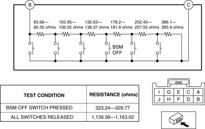
3. Verify that the resistance between BSM OFF switches B and C is as indicated in the table.

-
If the resistance cannot be verified as indicated in the table, replace the cluster switch.
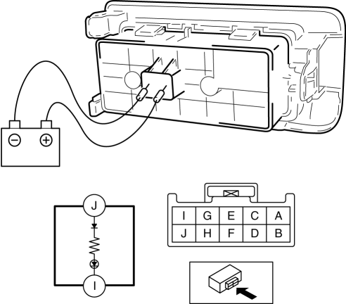
4. Apply battery positive voltage to BSM OFF switch terminal J, and connect terminal I to ground.

5. Verify that the LED illuminates.
-
If there is any malfunction, replace the cluster switch.
 Blind Spot Monitoring (Bsm) Off Switch
Purpose
The blind spot monitoring (BSM) system can be turned on or off optionally
by the driver.
Function
The switch operation signal is sent to the instrument cluster.
Co ...
 Blind Spot Monitoring (Bsm) System
Outline
The blind spot monitoring (BSM) system detects vehicles approaching from
the rear blind spots, and illuminates the BSM indicator light on the outer mirror
glass. When the BSM indi ...
Other materials:
Rear Wiper Arm And Blade Adjustment
1. Switch the ignition ON (engine off or on).
2. Operate the rear wiper.
3. Verify that the rear wiper is operating and stop the rear wiper.
4. Verify that the rear wiper is stopped at the auto-stop position.
5. Remove the rear wiper arm and blade..
6. Install the rear wiper arm to the ser ...
Rear Stabilizer Removal/Installation [2 Wd]
WARNING:
Verify that the rear crossmember is securely supported by a jack. If the
rear crossmember falls off, it can cause serious injury or death, and damage
to the vehicle.
CAUTION:
Performing the following procedures without first removing the rear ABS wheel-spee ...
Climate Control Unit Removal/Installation [Full Auto Air Conditioner]
NOTE:
The climate control unit prior to replacement stores the vehicle specification
information.
The new climate control unit does not store any vehicle specification information.
When the ignition is switched ON after the climate control unit is replaced,
the climate ...
