
Mazda CX-5 Service & Repair Manual: Auto Wiper System
Outline
-
The auto wiper system detects the amount of rainfall on the windshield and automatically operates the windshield wipers intermittently or at low/high speed and stops. Using the sensitivity adjustment function of the rain sensor, the operation speed and the intermittent period are adjusted automatically according to the amount of rainfall, vehicle speed, and other conditions.
-
The front body control module (FBCM) performs auto wiper system fail-safe..
Function
-
When the wiper and washer switch is in the AUTO position with the ignition switched ON (engine off or on), the auto wiper system operates the windshield wipers according to the amount of rainfall on the windshield, vehicle speed, and other conditions. The front body control module (FBCM) control the windshield wipers based on the windshield wiper operation signal from the rain sensor.
-
Intermittent operation control
-
When the rain sensor detects an amount of rainfall, the windshield wipers are operated once at low speed. Also, the intermittent period of the windshield wipers low-speed operation is switched in 5 levels according to the amount of rainfall detected.
-
Continuous low speed operation control
-
When the rain sensor detects an amount of rainfall greater than the amount required for intermittent operation control, the windshield wipers are operated continuously at low speed.
-
High speed operation control
-
When the vehicle speed is 4 km/h {2 mph} or more
and the rain sensor detects an amount of rainfall greater than the amount required for continuous low speed operation control, the windshield wipers are operated twice at high speed. Afterwards, if the rain sensor detects the necessary amount of rainfall for high speed operation, the windshield wipers are operated continuously at high speed. When the vehicle speed is 4 km/h {2 mph} or less
and the rain sensor detects an amount of rainfall greater than the amount required for continuous low speed operation, the windshield wipers are operated continuously at low speed.
-
Sensitivity adjustment function
-
The sensitivity adjustment function can adjust the rain sensor rain detection sensitivity by operation of the wiper and washer switch sensitivity adjustment volume.
-
When the windshield wipers are stopped during an interval and the sensitivity adjustment volume is operated in the direction of high sensitivity, the windshield wipers operate one time to notify the driver that the rain detection sensitivity has been changed.
Customize function
-
The auto wiper system customize function uses the rear body control module (RBCM) control to enable or disable the auto wiper functions.
-
If the auto wiper system is set to disabled, intermittent operation is performed.
-
Refer to WIPER AND WASHER SYSTEM CUSTOMIZATION for the detailed customization function.
On-board diagnostic function
-
If a malfunction occurs in the auto wiper control-related switch, sensor, and circuit, the front body control module (FBCM) detects DTCs. For details, refer to the diagnostic system (FBCM), DTC table (FBCM) in the workshop manual.
Structural view
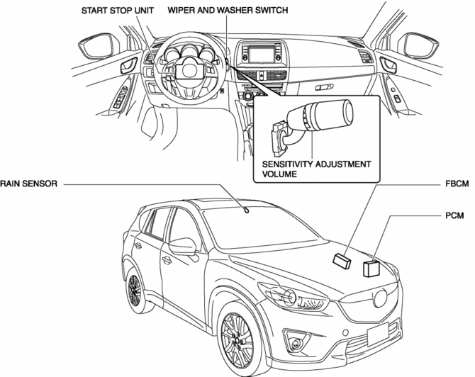
System wiring diagram
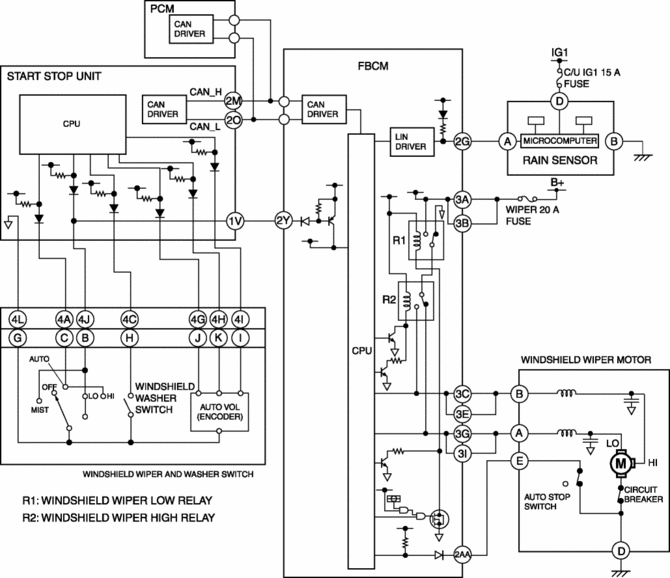
Operation
WARNING:
-
If servicing such as vehicle washing is performed with the ignition switched ON (engine off or on) and the wiper and washer switch in the AUTO position, the windshield wipers may operate automatically and your finger or hand is pinched, leading to an injury or wiper system malfunction. Always switch the ignition OFF (LOCK) or turn the wiper and washer switch to the OFF position before servicing.
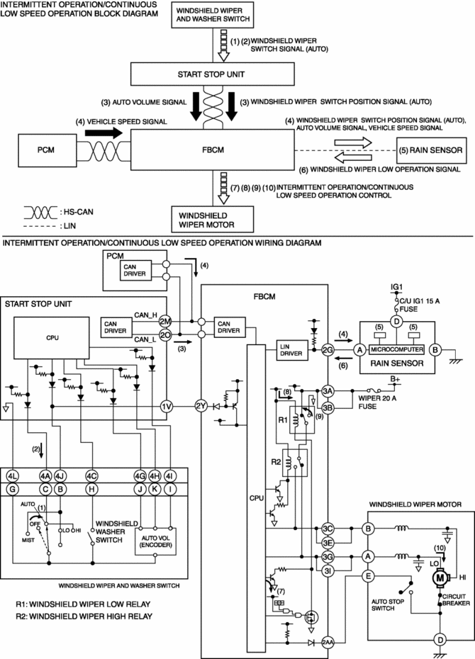
Intermittent Operation/Continuous Low Speed Operation
1. When the wiper and washer switch is moved to the AUTO position with the ignition switched ON (engine off or on) (1), the start stop unit detects a windshield wiper switch signal (AUTO).(2)
2. When the start stop unit detects a windshield wiper switch signal (AUTO), it sends a windshield wiper switch position signal (AUTO) and an AUTO volume signal to the front body control module (FBCM) as CAN signals.(3)
3. When the front body control module (FBCM) receives the windshield wiper switch position signal (AUTO), it sends the windshield wiper switch position signal (AUTO) and the AUTO volume signal to the rain sensor as LIN signals. At the same time, it sends a vehicle speed signal from the PCM to the rain sensor as a LIN signal.(4)
4. When the rain sensor receives the windshield wiper switch position signal (AUTO), it detects amount of rainfall and illumination level.(5)
5. The rain sensor determines the operation interval of the windshield wipers based on the detected rainfall amount and illumination level, and sends a windshield wiper low speed operation signal to the front body control module (FBCM).(6)
6. When the front body control module (FBCM) receives the windshield wiper low speed operation signal, it supplies the base current from the internal CPU to transistor A (7), and collector current flows from the internal power supply (8), turning the windshield wiper low relay on.(9)
7. When the windshield wiper low relay is turned on, current flows from the battery to the windshield wiper motor and the windshield wipers operate intermittently or continuously at low speed.(10)
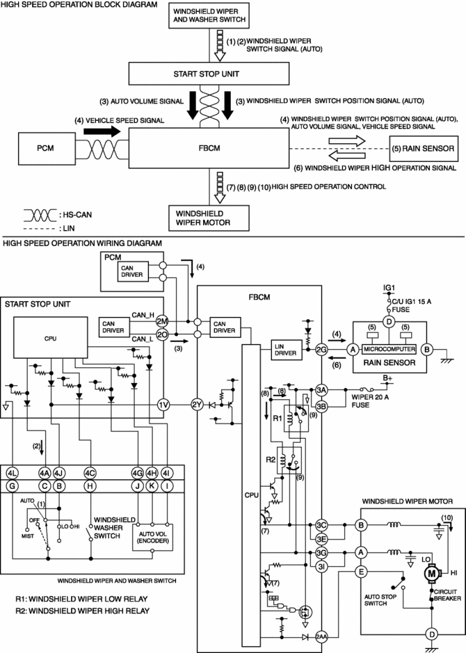
High Speed Operation
1. When the wiper and washer switch is moved to the AUTO position with the ignition switched ON (engine off or on) (1), the start stop unit detects a windshield wiper switch signal (AUTO).(2)
2. When the start stop unit detects the windshield wiper switch signal (AUTO), it sends the windshield wiper switch position signal (AUTO) and an AUTO volume signal to the front body control module (FBCM) as CAN signals.(3)
3. When the front body control module (FBCM) receives the windshield wiper switch position signal (AUTO), it sends the windshield wiper switch position signal (AUTO) and the AUTO volume signal to the rain sensor as LIN signals. At the same time, it sends a vehicle speed signal from the PCM to the rain sensor as a LIN signal.(4)
4. When the rain sensor receives the windshield wiper switch position signal (AUTO), it detects the amount of rainfall and illumination level.(5)
5. Based on the detected rainfall amount and illumination level, the rain sensor sends a windshield wiper high speed operation signal to the front body control module (FBCM).(6)
6. When the front body control module (FBCM) receives the windshield wiper high speed operation signal, it supplies the base current from the internal CPU to transistors A and B (7), and collector current flows from the internal power supply (8), turning the windshield wiper high relay on.(9)
7. When the windshield wiper high relay is turned on, current flows from the battery to the windshield wiper motor and the windshield wipers operate at high speed.(10)
 Wipers
...
 Rear Wiper Arm And Blade Adjustment
1. Switch the ignition ON (engine off or on).
2. Operate the rear wiper.
3. Verify that the rear wiper is operating and stop the rear wiper.
4. Verify that the rear wiper is stopped at the auto- ...
Other materials:
Front Combination Light Disassembly/Assembly
1. Disassemble in the order shown in the figure.
Halogen type
1
Short cord
(See Short Cord Removal Note.)
2
Parking/Front turn light bulb
(See PARKING/FRONT TURN LIGHT BULB REMOVAL/INSTALLATION.)
3
Headlight ...
PCM Inspection
Without Using the M-MDS
NOTE:
Because the PCM uses a waterproof connector, the inspection for the voltage/wave
pattern cannot be performed. The following values are for reference.
Terminal voltage table (Reference)
Terminal
Signal
C ...
Main Relay Control [Skyactiv G 2.0]
Outline
Supplies power to each part by switching the main relay on/off at the optimal
timing according to the vehicle conditions.
Block Diagram
Operation
When the ignition is switched ON, the main relay turns on and electrical
power is supplied to each sensor and devic ...
