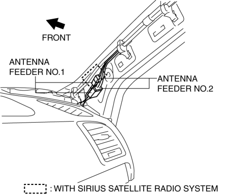
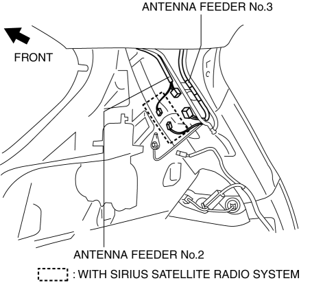
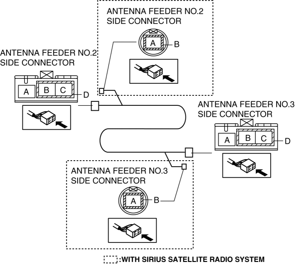
Mazda CX-5 Service & Repair Manual: Antenna Feeder No.2 Inspection
1. Disconnect the negative battery cable..
2. Remove the following parts:
a. A-pillar trim (RH).
b. Trunk board.
c. Trunk end trim (RH).
d. Rear scuff plate (RH).
e. Trunk side trim (RH).
3. Disconnect antenna feeder No.1.

4. Disconnect antenna feeder No.3.

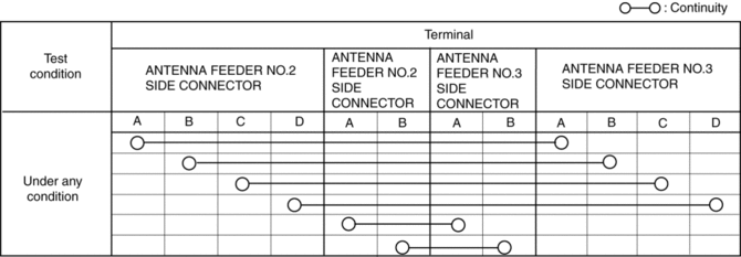
5. Verify that the continuity between antenna feeder No.2 terminals is as indicated in the table.

-
If not as indicated in the table, replace antenna feeder No.2.

 Antenna Feeder No.1 Removal/Installation
With audio system
1. Disconnect the negative battery cable..
2. Remove the following parts:
a. Side speaker grille (RH).
b. Tweeter (RH).
c. A-pillar trim.
d. Passenger-side front scuff pla ...
 Antenna Feeder No.2 Removal/Installation
Removal
1. Disconnect the negative battery cable..
2. Remove the following parts:
a. Sunroof seaming welt (with sunroof system).
b. A-pillar trim.
c. Front map light.
d. Sunvisor.
e. Fron ...
Other materials:
Front Lower Arm Removal/Installation
1. Remove the front under cover No.2..
2. Remove in the order indicated in the table.
3. Install in the reverse order of removal.
4. Inspect the wheel alignment and adjust it if necessary..
1
Front lower arm ball joint
2
Front lower arm ...
PID/Data Monitor Inspection [Adaptive Front Lighting System (Afs)]
1. Connect the M-MDS to the DLC-2.
2. After the vehicle is identified, select the following items from the initialization
screen of the M-MDS.
a. Select “DataLogger”.
b. Select “Modules”.
c. Select “AFS”.
3. Select the applicable PID from the PID table.
4. Verify the PID da ...
Liquid Crystal Display (LCD)
Outline
The LCD displays vehicle information in the instrument cluster.
The instrument cluster performs LCD fail-safe..
Function/Construction
The instrument cluster configures the indication of the LCD based on the
CAN signals sent from the related modules and displays ...
