Mazda CX-5 Service & Repair Manual: Airflow Mode Actuator [Full Auto Air Conditioner]
Purpose
-
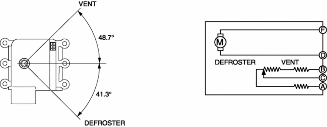
The airflow mode actuator moves the mode door in the A/C unit to switch the air vent.
Function
Door open/close function
-
The airflow mode actuator drives the motor based on the signal from the climate control unit and moves the mode door to the VENT, BI-LEVEL, HEAT, DEF/HEAT, or DEFROSTER position.
Door position detection function
-
The airflow mode actuator detects the changes in the mode door position using the potentiometer in conjunction with the motor drive and gives feedback to the climate control unit based on the electric signals.

Construction
-
A potentiometer-type airflow mode actuator has been adopted.
-
The airflow mode actuator is installed to the passenger's side in the A/C unit.
Operation
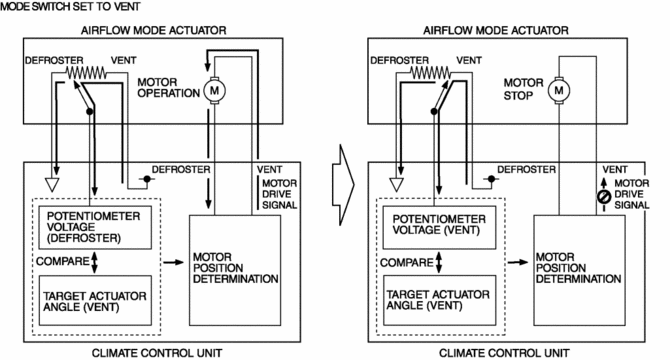
1. The climate control unit determines the airflow mode actuator target voltage based on the mode position determined by the airflow mode control.
2. The climate control unit compares the voltage detected by the potentiometer in the airflow mode actuator with the target voltage.
3. When the voltage detected by the potentiometer differs from the target voltage, the climate control unit outputs a motor drive signal.
4. When the voltage detected by the potentiometer is equal to the target voltage, the climate control unit stops the motor drive signal to the airflow mode actuator.

Fail-safe
-
Function not equipped.
 Airflow Mode Actuator Removal/Installation [Full Auto Air Conditioner]
1. Disconnect the negative battery cable..
2. Remove the following parts:
a. Dashboard under cover.
b. Glove compartment.
3. Disconnect the airflow mode actuator connector.
4. Remove the scr ...
 Airflow Mode Control [Full Auto Air Conditioner]
Purpose
The airflow mode control changes the airflow mode according to the vehicle
environment.
Function
The airflow mode control drives the airflow mode actuator according to t ...
Other materials:
Rear Lateral Link Removal/Installation
1. Disconnect the rear stabilizer control link lower side nut..
2. Remove in the order indicated in the table.
3. Install in the reverse order of removal.
4. Inspect the wheel alignment and adjust it if necessary..
1
Rear lateral link outer bolt
...
Operating Tips
Operate the climate control system with the engine running.
• To prevent the battery from being discharged,
do not leave the fan control dial on for a long period of time with the ignition
switched ON when the engine is not running.
• Clear all obstructions such as leaves, snow
and ice f ...
Power Window Motor Inspection
Front driver side
1. Disconnect the negative battery cable..
2. Remove the inner garnish..
3. Remove the front door trim..
4. Disconnect the power window motor connector.
5. Apply battery positive voltage and connect the ground to power window motor
terminals E and F, and then inspect the ...
