Mazda CX-5 Owners Manual: Accessory Sockets
Only use genuine Mazda accessories or the equivalent requiring no greater than 120 W (DC 12 V, 10 A).
Front
The ignition must be switched to ACC or ON.

Center, Rear
The accessory sockets can be used regardless of whether the ignition is on or off.


CAUTION
●To prevent accessory socket damage or electrical failure, pay attention to the following:
● Do not use accessories that require more than 120 W (DC 12 V, 10 A).
● Do not use accessories that are not genuine Mazda accessories or the equivalent.
● Close the cover when the accessory socket is not in use to prevent foreign objects and liquids from getting into the accessory socket.
● Correctly insert the plug into the accessory socket.
● Do not insert the cigarette lighter into the accessory socket.
● Noise may occur on the audio playback depending on the device connected to the accessory socket.
● Depending on the device connected to the accessory socket, the vehicle's electrical system may be affected, which could cause the warning light to illuminate.
Disconnect the connected device and make sure that the problem is resolved. If the problem is resolved, disconnect the device from the socket and switch the ignition off. If the problem is not resolved, consult an Authorized Mazda Dealer.
NOTE
To prevent discharging of the battery, do not use the socket for long periods with the engine off or idling.
Connecting the accessory socket
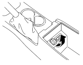
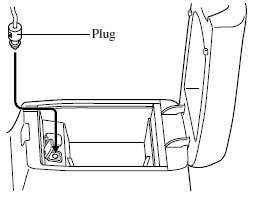
1. Open the lid." 2. Pass the connection plug cord through the cutout of the console and insert the plug into the accessory socket.

 Clock
Clock
The time is displayed when the ignition is switched to ACC or ON.
With Fully Automatic Type Climate Control System
With Manual Type Climate Control System
Time setting
1. Switch the ignition A ...
 Cup Holder
WARNING
Never use a cup holder to hold hot liquids while the vehicle is moving:
Using a cup holder to hold hot liquids while the vehicle is moving is dangerous.
If the contents spill, you could be ...
Other materials:
Seat Weight Sensor Calibration [Two Step Deployment Control System]
CAUTION:
If any of the following work is performed, perform the seat weight sensor
calibration using the M-MDS.
Replacement with a new seat weight sensor
Replacement with a new seat weight sensor control module
Replacement with new passenger-side seat pa ...
Engine Oil Solenoid Valve
Purpose, Function
The engine oil solenoid valve switches the hydraulic transmission passage
in accordance with the driving conditions and the oil pump drive resistance
is reduced by controlling oil pump discharging pressure in two steps.
Construction
The engine oil solenoid ...
Rear Center Seat Belt Removal/Installation
CAUTION:
The ELR (emergency locking retractor) has a spring that will unwind if the
retractor cover is removed. The spring cannot be rewound by hand. If this occurs,
the ELR will not work properly. Therefore, do not disassemble the retractor.
1. Press the release switch, then dis ...
