Mazda CX-5 Service & Repair Manual: Power Window Main Switch
Purpose
-
Remote control of door glass open/close and power outer mirror adjustment are possible with occupant seated in the cabin.
Function
Power window main switch
-
Manual
-
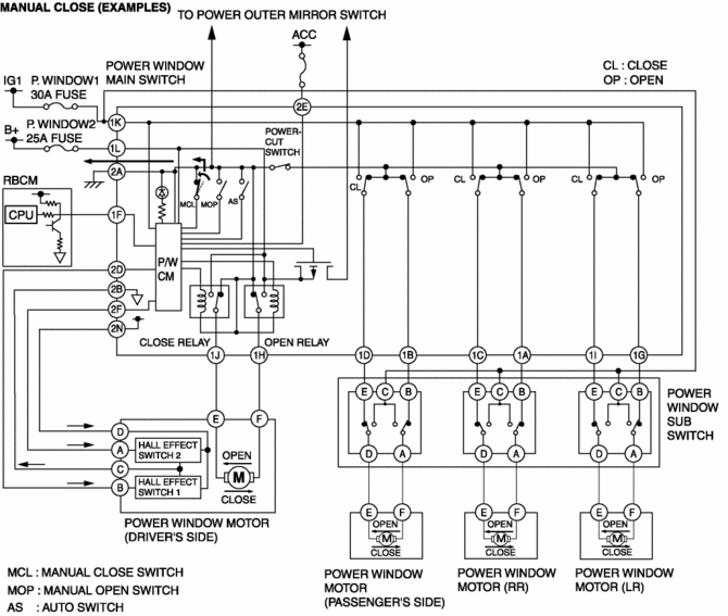
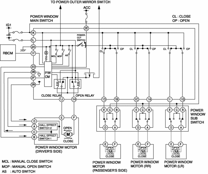
When the power window main switch is operated for manual open/close operation, it sends a manual open/close signal to the P/W CM (power window control module).
-
Auto
-
When the power window main switch is operated for auto open/close operation, it sends an auto open/close signal to the P/W CM.
-
Power cut
-
When the power-cut switch is pressed, it disables the operation of the power window subswitches for the front and rear passenger seats.
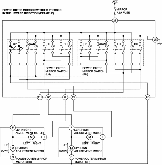
Power outer mirror switch
-
Up-down/left-right adjustment
-
The power outer mirror switch switches the contact point according to the switch operation. As a result, the circuit to the up-down/left-right adjustment motor is switched.
-
Left/right selection
-
The power outer mirror switch is used to select the side on which adjustment of the power outer mirror glass is desired.
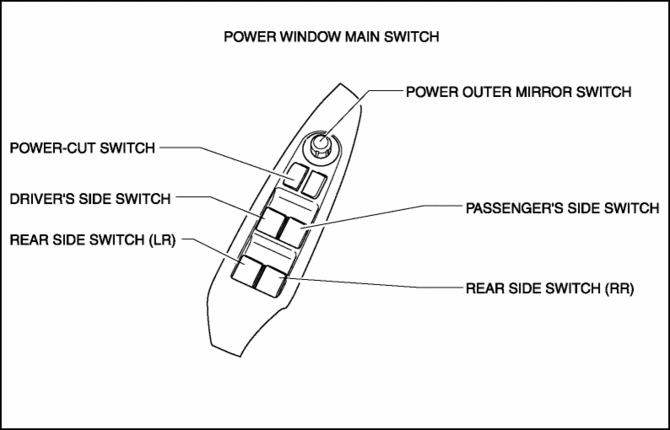
Construction
-
The power window main switch consists of the following parts:
-
Driver's side switch
-
Passenger's side switch
-
Rear side switch (LR)
-
Rear side switch (RR)
-
Power-cut switch
-
Power outer mirror switch
-
Up/down/left/right adjustment
-
Left/right selection
-
The power window main switch has a built-in P/W CM (power window control module), and controls the auto reverse pinch protection, IG OFF timer, and IG OFF timer cancel functions.
Operation
Power window main switch
1. Contact points for door glass opening/closing can be changed by operating the power window main switch. The P/W CM monitors the operation conditions of the driver's side switch and power window motor.
Power-cut switch
1. The power window main switch turns off when the power-cut switch is operated for lock operation.
Power outer mirror switch
1. Up/down/left/right contact points for the power outer mirror can be switched by operating the power outer mirror switch.
Fail-safe
-
Function not equipped
 Glass/Windows/Mirrors
Outline
The following glass has been adopted.
Windshield
Front door glass
Rear door glass
Rear door quarter glass
Quarter window glass
...
 Power Window Main Switch Inspection
1. Disconnect the negative battery cable..
2. Remove the following parts:
a. Inner garnish. (driver's side).
b. Front door trim. (driver's side).
c. Power window main switch.
3. Conn ...
Other materials:
Pre Tensioner Seat Belt [Two Step Deployment Control System]
Purpose
The pre-tensioner seat belt retracts and tightens the seat belt webbing to
protect the front passengers during a collision.
Function
The pre-tensioner seat belts operate (deploy) based on the operation signal
from the SAS control module to instantly retract and tigh ...
Shroud Side Member Removal [Panel Replacement]
Symbol Mark
Removal Procedure
1. Drill the 3 locations indicated by (A) shown in the figure.
2. Drill the 8 locations indicated by (B) and 2 locations indicated by (C) shown
in the figure.
NOTE:
When drilling the 3 locations indicated by (A) and 2 locations indicated
by (C) sh ...
Location of the Tire Label (Placard)
You will find the tire label containing tire inflation pressure by tire size
and other important information on the driver's side B-pillar or on the edge of
the driver's door frame.
SAMPLE
Recommended Tire Inflation Pressure
On the tire label you will find the recommended tire infla ...
