Mazda CX-5 Service & Repair Manual: Electric Variable Valve Timing Motor/Driver Removal/Installation
WARNING:
-
A hot engine can cause severe burns. Turn off the engine and wait until it is cool before servicing.
CAUTION:
-
Applying excessive force (force of 100 N {10.2 kgf, 22.5 lbf} or more) to the electric variable valve timing motor/driver may cause a malfunction. When servicing, be careful not to apply excessive force to the electric variable valve timing motor/driver using other parts or tools.
-
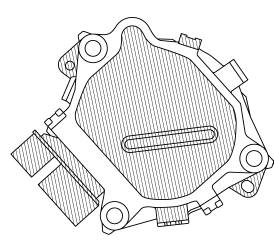
Do not disassemble the electric variable valve timing motor/driver because it is a precision unit.
1. Disconnect the negative battery cable..
2. Remove the plug hole plate..
3. Remove in the order indicated in the table.
4. Install in the reverse order of removal.
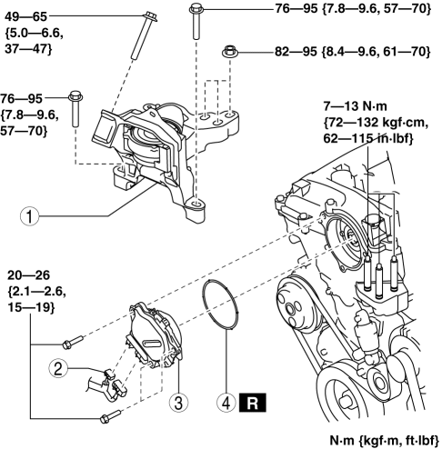
|
1 |
No. 3 engine mount (See No.3 Engine Mount Removal Note.) (See No.3 Engine Mount Installation Note.) |
|
2 |
Electric variable valve timing motor/driver connector |
|
3 |
Electric variable valve timing motor/driver (See Electric Variable Valve Timing Motor/Driver Installation Note.) |
|
4 |
O-ring |
No.3 Engine Mount Removal Note
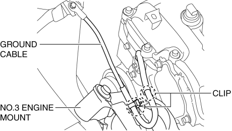
1. Remove the clips shown in the figure and set the ground cable aside.
2. Remove the front under cover No.2..
CAUTION:
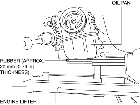
-
To prevent deformation of the oil pan, support the engine using the following methods.
-
When using an engine lifter, insert rubber of appropriate size (approx. 20 mm {0.79 in} thickness) between the engine lifter and the oil pan to support the oil pan.
-
When using a garage jack, place rubber of appropriate size (approx. 20 mm {0.79 in} thickness) on a batten which is large enough to cover the oil pan to support the oil pan.
3. Before removing the No.3 engine mount, support the engine (oil pan) using a commercially available engine lifter or garage jack.
CAUTION:
-
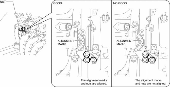
Slots have been adopted for the No.3 engine mount installation holes. If the No.3 engine mount is deviated from the original position when installing the No.3 engine mount, engine noise or vibration could increase. Before removing the No.3 engine mount, place alignment marks on the No.3 engine mount and body so that they can be assembled to the same positions as before removal.
4. Place alignment marks on the locations shown in the figure so that they can be assembled to the same positions as before removal.
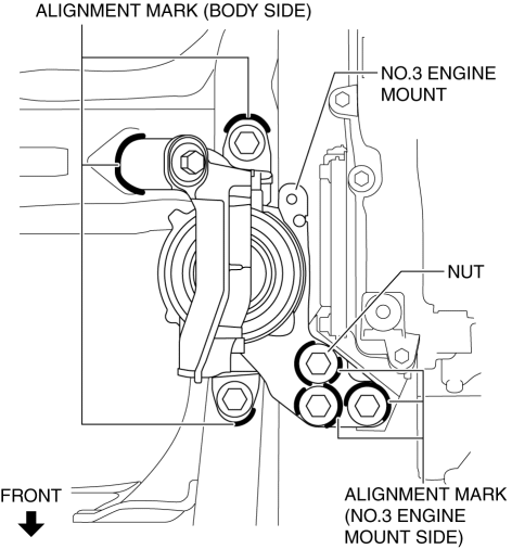
NOTE:
-
Paint so that the No.3 engine mount is framed on the body side and the outline of the nut is framed on the No.3 engine mount side.
5. Remove the No. 3 engine mount.
Electric Variable Valve Timing Motor/Driver Installation Note
1. Install a new O-ring to the O-ring installation groove of the engine front cover.
CAUTION:
-
To prevent damage to the electric variable valve timing motor/driver, do not apply excessive force (force of 100 N {10.2 kgf, 22.5 lbf} or more) to the shaded areas shown in the figure.
2. Install the electric variable valve timing motor/driver using the following procedures.
NOTE:
-
The eccentric shaft on the electric variable valve timing actuator side can be rotated to the left and right.
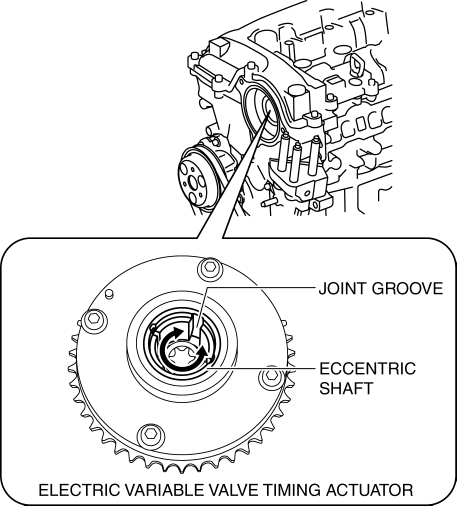
-
The electric variable valve timing motor/driver can be assembled with the joint groove of the eccentric shaft in any position, and it will not lead to vehicle damage or performance reduction.
a. Before installation, rotate the joint of the end of the electric variable valve timing motor so that it is aligned to the joint groove on the electric variable valve timing actuator side.
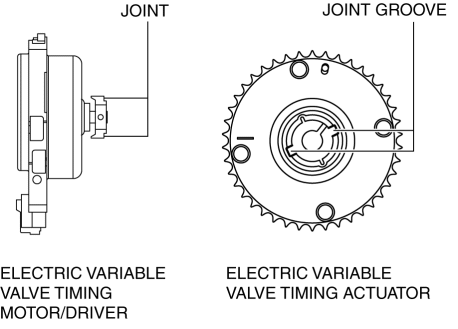
b. Engage the joint on the end of the electric variable valve timing motor with the joint groove on the electric variable valve timing actuator side.
c. Attach the seal surface.
d. Tighten the electric variable valve timing motor/driver installation bolts.
-
Tightening torque
-
20—26 N·m {2.1—2.6 kgf·m, 15—19 ft·lbf}
No.3 Engine Mount Installation Note
CAUTION:
-
If the No.3 engine mount is deviated from the original position when installing the No.3 engine mount, engine noise or vibration could increase. When installing the No.3 engine mount, align the alignment mark placed during removal and install it to the original position.
NOTE:
-
When replacing the No.3 engine mount, place a mark at the same position as the one placed before removal.
-
If the No.3 engine mount nut is loosened, tighten the stud bolts of the engine front cover because they may be loosened.
1. Tighten the stud bolts of the engine front cover.
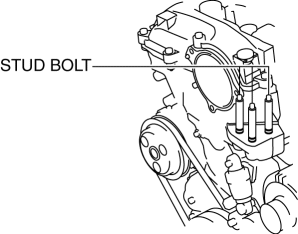
-
Tightening torque
-
7—13 N·m {72—132 kgf·cm, 62—115 in·lbf}
2. Temporarily tighten the No.3 engine mount installation bolts and nuts using the following procedure:
a. Align the alignment marks on the body side and No.3 engine mount, and temporarily tighten the bolts shown in the figure.
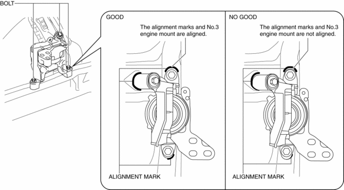
b. Temporarily tighten the nuts shown in the figure while aligning the alignment marks of the No.3 engine mount and nuts.
NOTE:
-
If the alignment marks are not aligned, align the alignment marks while slightly moving the engine and temporarily tighten the nuts.
3. Tighten the No.3 engine mount installation bolts and nuts in the order shown in the figure.
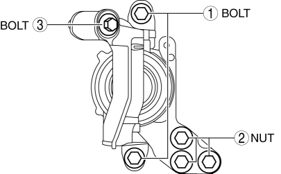
|
No. |
Tightening torque |
|
1 |
76—95 N·m {7.8—9.6 kgf·m, 57—70 ft·lbf} |
|
2 |
82—95 N·m {8.4—9.6 kgf·m, 61—70 ft·lbf} |
|
3 |
49—65 N·m {5.0—6.6 kgf·m, 37—47 ft·lbf} |
4. Remove the engine lifter or garage jack.
5. Install in the reverse order of removal.
 Electric Variable Valve Timing Motor/Driver Inspection
WARNING:
A hot engine can cause severe burns. Turn off the engine and wait until it
is cool before servicing.
CAUTION:
Do not disassemble the electric variable valve timing mo ...
 Engine Abbreviations
AAS
Active Adaptive Shift
ABS
Antilock Brake System
ABDC
After Bottom Dead Center
ACC
Access ...
Other materials:
Washer Fluid Level Sensor
Purpose
The washer fluid-level sensor illuminates the low washer fluid level warning
light when the washer fluid level is lowered.
Function
The washer fluid-level sensor detects the decrease in the washer fluid level.
Construction
The washer fluid-level sensor con ...
DRL (Daytime Running Light) System
Outline
The DRL system automatically switches the headlights to HI beams (50% dim)
or illuminates the DRL bulb when the ignition is switched ON (engine on), the
parking brake is released, and the shift lever is in a position other than P
(ATX).
The front body control module ( ...
Hood Disassembly/Assembly
1. Disassemble in the order indicated in the table.
1
Fastener
2
Hood insulator
3
Shroud seaming welt
4
Weather strip parting seal
5
Hood component
...
