Mazda CX-5 Service & Repair Manual: Wheel Apron Component Installation [Panel Replacement]
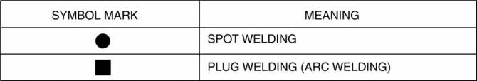
Symbol Mark
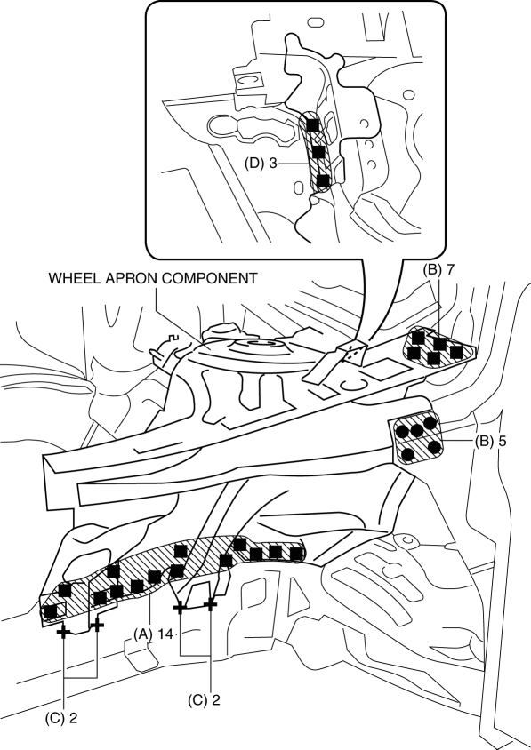
Installation Procedure
1. When installing new parts, measure and adjust the body as necessary to conform with standard dimensions.
2. Drill holes for the plug welding before installing the new parts.
3. After temporarily installing new parts, make sure the related parts fit properly.
4. Plug weld the 14 locations indicated by (A) from the front wheel housing side shown in the figure.
5. Spot weld the 5 locations indicated by (B) shown in the figure.
6. Arc weld the 4 locations indicated by (C) shown in the figure.
7. Plug weld the 3 locations indicated by (D) shown in the figure.
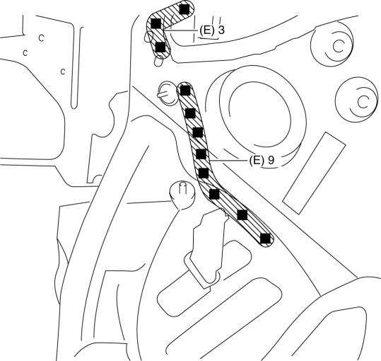
8. Plug weld the 12 locations indicated by (E) from the inside shown in the figure, then install the wheel apron component.
 Wheel Alignment Pre Inspection
1. Park the vehicle on level ground, in an unloaded condition*, with the wheels
straight forward.
*: Unloaded condition.....Fuel tank is full. Engine coolant and engine oil are
at specified leve ...
 Wheel Apron Component Removal [Panel Replacement]
Symbol Mark
Removal Procedure
1. Drill the 14 locations indicated by (A) from the front wheel housing side
shown in the figure.
2. Drill the 11 locations indicated by (B) shown in the figure ...
Other materials:
Air Bag System Service Warnings [Standard Deployment Control System]
Air Bag Module Inspection
Inspecting an air bag module using a tester can operate (deploy) the air
bag module, which may cause serious injury. Do not use a tester to inspect an
air bag module. Always use the on-board diagnostic function to diagnose the
air bag module for malfunctions ...
Child-Restraint System Installation
Child-Restraint System Types
In this owner's manual, explanation of child-restraint systems is provided for
the following three types of popular childrestraint systems: infant seat, child
seat, booster seat.
NOTE
• Installation position is determined
by the type of child-restraint sys ...
Evaporative Emission (Evap) Control System
Purpose, Outline
Prevents release of evaporative gas into the atmosphere.
The intake manifold vacuum introduces evaporative gas to the intake manifold
via the charcoal canister and the purge solenoid valve.
System Diagram
U.S.A. and CANADA
Except U.S.A. and CANADA
...
