
Mazda CX-5 Service & Repair Manual: Washer Fluid Level Sensor
Purpose
-
The washer fluid-level sensor illuminates the low washer fluid level warning light when the washer fluid level is lowered.
Function
-
The washer fluid-level sensor detects the decrease in the washer fluid level.
Construction
-
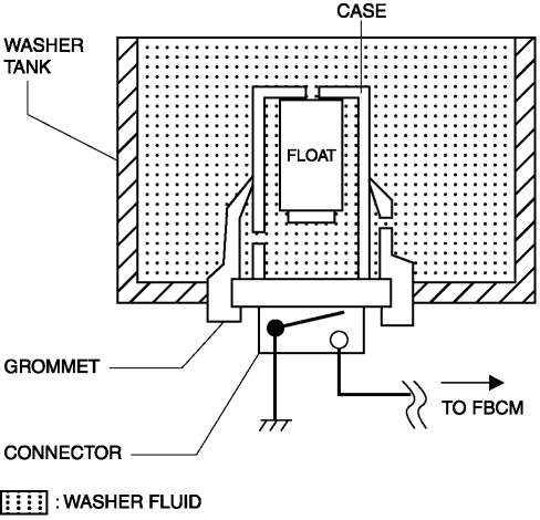
The washer fluid-level sensor consists of the following parts:
-
Connector (switch)
-
Float
-
Grommet
-
Case
-
The float has an integrated magnet which creates a magnetic field.
Operation
When washer fluid is added
1. Washer fluid enters the case of the washer fluid-level sensor, the float rises, and the connector switch turns off.
When washer fluid is decreased
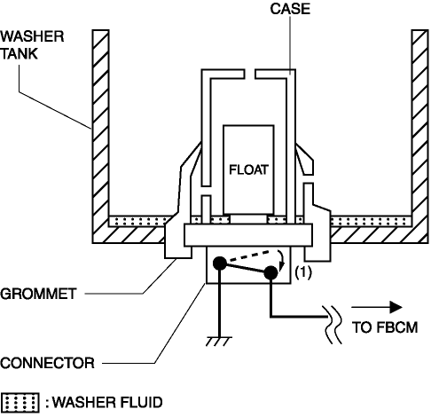
1. When washer fluid inside the case of the washer fluid-level sensor decreases, the float comes close to the connector switch.
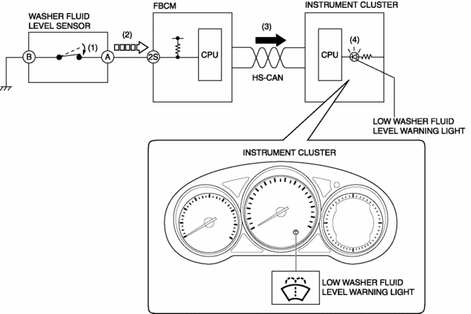
2. When the float approaches the switch, the magnetic field inside the float acts on the switch and the switch turns on. (1)
3. When the switch is turned on, the front body control module (FBCM) detects that the washer fluid level is lowered (2) and sends a low washer fluid level warning light illumination request signal to the instrument cluster as a CAN signal. (3)
4. When the instrument cluster receives the low washer fluid level warning light illumination request signal, it illuminates the low washer fluid level warning light. (4)
Fail-safe
-
Function not equipped.
 Windshield Washer Nozzle Removal/Installation
1. Remove the following parts:
a. Windshield wiper arm and blade.
b. Cowl grille.
2. Disconnect the windshield washer hose from the windshield washer nozzle..
3. While pressing windshield was ...
 Washer Fluid Level Sensor Inspection
1. Disconnect the negative battery cable..
2. Set the front over fender aside..
3. Set the mudguard (RH) aside..
4. Remove the front bumper..
5. Inspect for continuity according to washer flui ...
Other materials:
HomeLink Wireless Control System
NOTE
HomeLink and HomeLink house are registered trademarks of Johnson Controls.
The HomeLink system replaces up to 3 hand-held transmitters with a single builtin
component in the auto-dimming mirror.
Pressing the HomeLink button on the auto-dimming mirror activates garage doors,
gates and oth ...
Pre Tensioner Seat Belt [Two Step Deployment Control System]
Purpose
The pre-tensioner seat belt retracts and tightens the seat belt webbing to
protect the front passengers during a collision.
Function
The pre-tensioner seat belts operate (deploy) based on the operation signal
from the SAS control module to instantly retract and tigh ...
Active Command Modes Inspection [Rear Body Control Module (Rbcm)]
1. Connect the M-MDS to the DLC-2.
2. After the vehicle is identified, select the following items from the initialization
screen of the M-MDS.
a. Select “DataLogger”.
b. Select “Modules”.
c. Select “R_BCM”.
3. Select the simulation items from the PID table.
4. Perform the a ...
