Mazda CX-5 Service & Repair Manual: Underbody Dimensions [Dimensions]
NOTE:
-
The following figure is a bottom view.
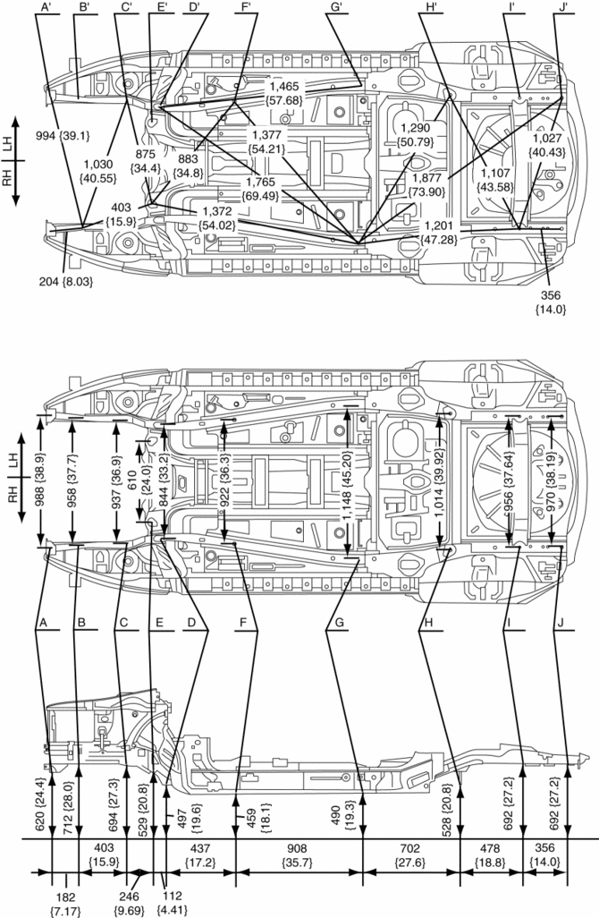
|
Point symbol |
Designation |
Hole diameter or bolt or nut size mm {in} |
|
A |
Front crossmember installation hole |
?24 {0.94} |
|
B |
Front side frame datum hole |
?16 {0.63} |
|
C |
Front crossmember installation hole |
?22.5 {0.886} |
|
D |
Front crossmember installation hole |
?19 {0.75} |
|
E |
Front crossmember installation hole |
?22 {0.87} |
|
F |
Front B frame datum hole |
?16 {0.63} |
|
G |
Front B frame datum hole |
?25 {0.98} |
|
H |
Rear crossmember mounting bolt |
M12 |
|
I |
Rear side frame datum hole |
?10 {0.39} |
|
J |
Rear side frame datum hole |
?30 {1.2} |
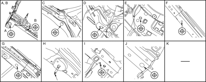
 Splash Shield Removal/Installation
Front
Front splash shield No.1
1. Set the mudguard aside..
2. Remove fasteners A.
3. Remove the front splash shield No.1.
4. Install in the reverse order of removal.
Front splash shield ...
 Upper Cowl Side Reinforcement Installation [Panel Replacement]
Symbol Mark
Installation Procedure
1. When installing new parts, measure and adjust the body as necessary to conform
with standard dimensions.
2. Drill holes for the plug welding before inst ...
Other materials:
Engine Disassembly/Assembly
CAUTION:
When the transaxle is installed, do not suspend the engine. Otherwise, the
SST installation area of the cylinder head may be damaged due to excess weight.
Only suspend the engine after separating the engine and transaxle.
Applying excessive force (force of 100 N {10.2 ...
Climate Control Unit [Manual Air Conditioner]
Purpose
The climate control unit performs air conditioning according to the operation
by the users and the driving conditions of the vehicle.
Function
The climate control unit determines optimum air-conditioning based on the
input signals from each sensor and the control mo ...
Efficient Installation Of Body Panels
Checking Preweld Measurements And Watching
Align to the standard reference dimensions, based upon the body dimensions
illustration, so that new parts are installed in the correct position.
Welding Notes
For the number of weld points, welding should be performed in accord ...
