Mazda CX-5 Service & Repair Manual: Side Sill Panel Installation [Panel Replacement]
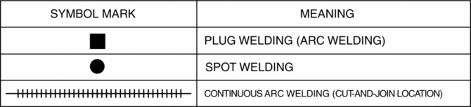
Symbol Mark
Installation Procedure
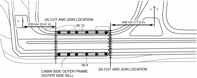
Side sill (front side)
1. When installing new parts, measure and adjust the body as necessary to conform with standard dimensions.
2. Drill holes for the plug welding before installing the new parts.
3. After temporarily installing new parts, make sure the related parts fit properly.
4. Cut and join the 2 locations indicated by (A) shown in the figure.
5. Plug weld the 18 locations indicated by (B) shown in the figure, then cabin side outer frame (outer side sill).
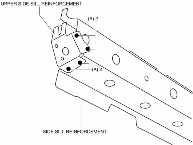
Side sill (component)
1. When installing new parts, measure and adjust the body as necessary to conform with standard dimensions.
2. Drill holes for the plug welding before installing the new parts.
3. After temporarily installing new parts, make sure the related parts fit properly.
4. Drill the 4 locations indicated by (A) shown in the figure, then remove the upper side sill reinforcement from the new side sill reinforcement.
5. Plug weld the 32 locations indicated by (B) shown in the figure.
6. Plug weld the 3 locations indicated by (C) shown in the figure, then install the side sill reinforcement.

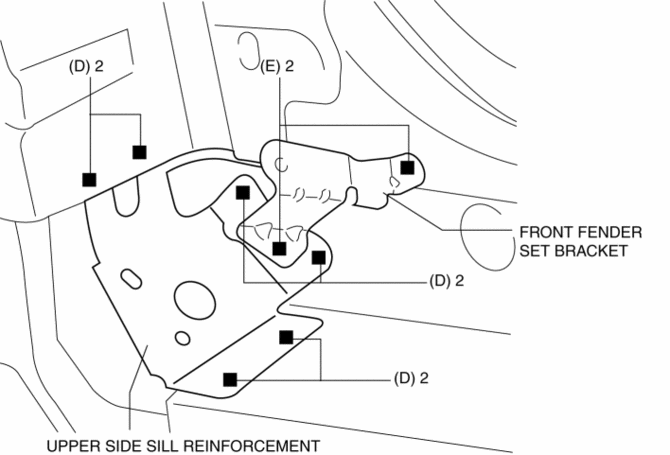
7. Plug weld the 6 locations indicated by (D) shown in the figure, then install the upper side sill reinforcement.
8. Plug weld the 2 locations indicated by (E) shown in the figure, then install the front fender set bracket.
9. Cut and join the 3 locations indicated by (F) shown in the figure.
10. Plug weld the 120 locations indicated by (G) shown in the figure, then install the cabin side outer frame (outer side sill).

 Side Garnish Removal
Front
1. Insert a tape-wrapped flathead screwdriver in the position shown in the figure,
move it in the direction of the arrow (1) to remove the clip A.
2. Slide the side garnish in the direc ...
 Side Sill Panel Removal [Panel Replacement]
Symbol Mark
Removal Procedure
Side sill (front side)
1. Rough cut the 2 locations indicated by (A) shown in the figure.
2. Drill the 18 locations indicated by (B) shown in the figure.
3 ...
Other materials:
Magnet Clutch [Full Auto Air Conditioner]
Purpose
The magnetic clutch transmits the rotation force from the engine to the shaft
in the A/C compressor.
Function
The magnetic clutch engages or disengages the magnetic clutch and the A/C
turns on or off by switching the power transmission from the engine.
C ...
Resistor Inspection [Manual Air Conditioner]
1. Verify that the resistance between the resistor terminals is as shown in the
table.
If there is any malfunction, replace the resistor.
Terminal
Resistance (ohm)
A—D
0.35—0.41
A—B
0. ...
Clutch Fluid Inspection [C66 M R]
NOTE:
A common reserve tank is used for the clutch system and brake system.
1. Verify that the clutch fluid is between the MIN mark and the MAX mark.
Verify that there is no clutch fluid leakage then add clutch fluid to the
level between the MIN mark and the MAX mark..
...
