Mazda CX-5 Service & Repair Manual: Shroud Side Member Installation [Panel Replacement]
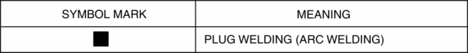
Symbol Mark
Installation Procedure
1. When installing new parts, measure and adjust the body as necessary to conform with standard dimensions.
2. Drill holes for the plug welding before installing the new parts.
3. After temporarily installing new parts, make sure the related parts fit properly.
4. Plug weld the 8 locations indicated by (A) and 2 locations indicated by (B) shown in the figure.
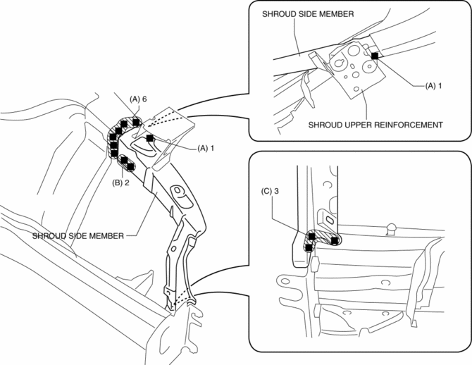
5. Plug weld the 3 locations indicated by (C) shown in the figure, then install the shroud side member.
 Shroud Panel Removal/Installation
CAUTION:
Since the servicing is performed with the hood open, secure the hood using
a piece of wood to prevent it from falling.
1. Disconnect the negative battery cable..
2. Remove ...
 Shroud Side Member Removal [Panel Replacement]
Symbol Mark
Removal Procedure
1. Drill the 3 locations indicated by (A) shown in the figure.
2. Drill the 8 locations indicated by (B) and 2 locations indicated by (C) shown
in the figure.
...
Other materials:
Powertrain System [C66 M R]
Purpose, Function
The powertrain mechanism changes the gear combination by engaging or releasing
the clutch hub and gear, and changes the power transmission route. Because of
the change in the power transmission route, the drive force (speed, torque,
rotation direction) input from th ...
Fuel Pump Control Module
Purpose, Function
Controls the voltage applied to the fuel pump for reducing fuel pump load
and improving fuel economy.
Controls the voltage applied to the fuel pump based on the control signal
from the PCM.
Construction
The fuel pump control module is installed bel ...
Front Door Garnish Removal/Installation
WARNING:
Using a utility knife with bare hands can cause injury. Always wear gloves
when using a utility knife.
1. Using a tape-wrapped fastener remover, remove clips A in the direction of
arrow (1), (2) shown in the figure.
2. Remove the double-sided adhesive tape in the positi ...
