Mazda CX-5 Service & Repair Manual: Shift Lock System [Fw6 A EL, Fw6 Ax EL]
Purpose, Function
-
The shift-lock system operates when the ignition is switched to ON and the brake pedal is not depressed, and inhibits the selector lever from being shifted from the P position to other positions.
-
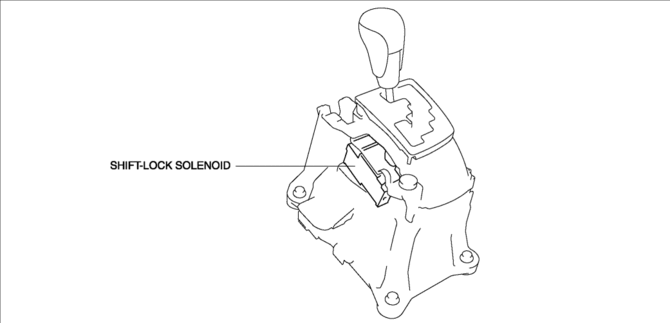
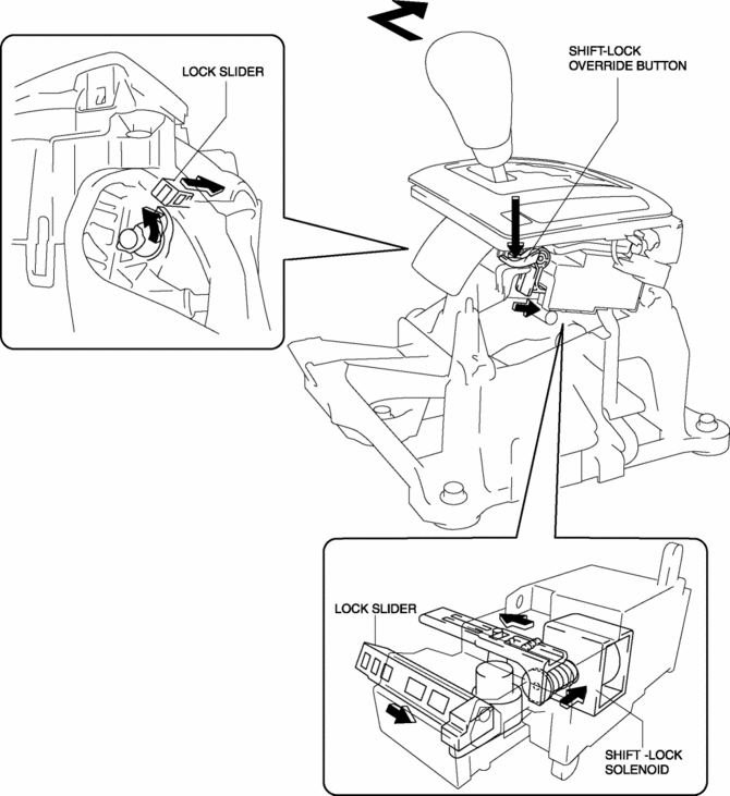
If the shift-lock cannot be released by the normal operation, it can be released manually by inserting a flathead screwdriver into the shift-lock release hole (emergency manual shift-lock release system).
Construction
Wiring diagram
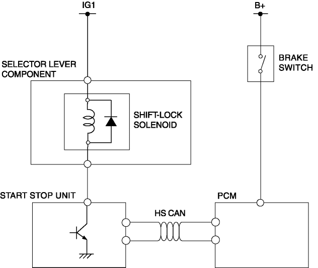
Structural view
Operation
Shift-lock Release Conditions
-
The shift-lock is released when all of the following conditions are met (except shift-lock release system is operated manually).
-
Selector lever is in P position
-
Ignition is switched to ON
-
Brake pedal is depressed (brake light switch is on)
Shift-lock operation conditions (shift-lock release conditions not satisfied)
-
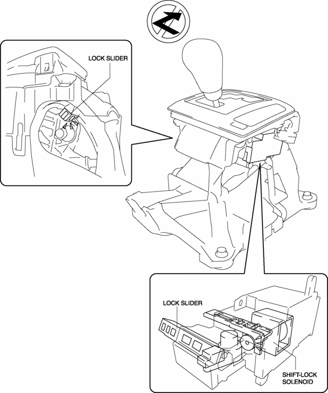
When the shift-lock release conditions are not met, the shift-lock operates.
-
Because there is no energization to the shift-lock solenoid at this time, the shift-lock solenoid is not energized.
-
As a result, the lock slider is positioned where it restricts the selector lever movement and the selector lever cannot be moved to any position other than P.
Shift-lock release (Shift-lock release conditions are satisfied)
-
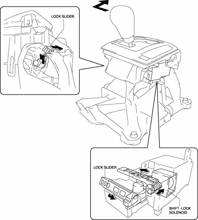
When the shift-lock release conditions are met, the shift-lock does not operate.
-
At this time, the shift-lock solenoid is energized because there is energization to the shift-lock solenoid.
-
As a result, the selector lever can be moved to any position other than P by moving the lock slider to a position where it does not restrict the selector lever movement.
Emergency Manual shift-lock release system operation
-
The emergency manual shift-lock release system can be released manually even if the shift-lock release conditions are not met.
-
The lock slider restriction can be cancelled forcibly by pressing the shift-lock override button using a flathead screwdriver.
-
As a result, the selector lever can be moved to any position other than P.
 Shift Lock System Inspection
Shift-Lock System Inspection
1. Switch the ignition ON (engine off).
2. Shift the selector lever to the P position.
3. Verify that the selector lever cannot be shifted from P to R position when
...
 Shift Pressure Control (Direct Electric Shift Control) [Fw6 A EL, Fw6 Ax EL]
Outline
The TCM drives shift solenoids No.1, 2, 3, 4, the pressure control solenoid,
and the on/off solenoid based on inputs signals from each switch and sensor,
and performs direct elect ...
Other materials:
Identification Number Locations
Vehicle Identification Number (VIN)
If the VIN plate is adhered to the dashboard, it is located in the position
shown in the figure.
Engine Type/Number
SKYACTIV-G 2.0
SKYACTIV-G 2.5
...
Dashboard Removal/Installation
1. Disconnect the negative battery cable..
2. Remove the following parts:
a. Windshield wiper arm and blade.
b. Cowl grille.
c. Windshield wiper motor.
d. Front scuff plate.
e. Front side trim.
f. Glove compartment.
g. Dashboard under cover.
h. Decoration panel.
i. Center panel. ...
Tire Pressure Monitoring System Warning Light
Purpose, Function
The tire pressure monitoring system warning light notifies the driver that
it was determined that a tire pressure has decreased below the specified value
based on the initialization.
The tire pressure monitoring system warning light notifies the driver that
...
