Mazda CX-5 Service & Repair Manual: Shift Control Module Removal/Installation [C66 M R]
Removal
1. Shift the shift lever to the neutral position.
2. Remove the plug hole plate..
3. Disconnect the negative battery cable..
4. Remove the air cleaner and air hose as a single unit..
5. Remove the battery and battery tray..
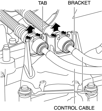
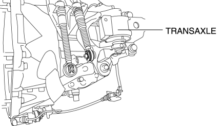
6. Disconnect the control cable from the transaxle.
a. Pull the lock pin in the direction of the arrow shown in the figure and release the control cable end lock.
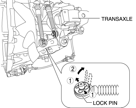
b. Press the tabs on the control cable and disconnect the control cable from the bracket on the transaxle.
7. Remove the neutral switch in the order shown in the figure
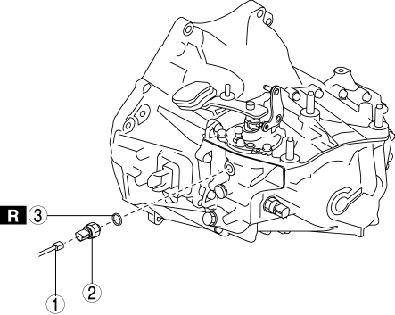
|
1 |
Connector |
|
2 |
Neutral switch |
|
3 |
Gasket |
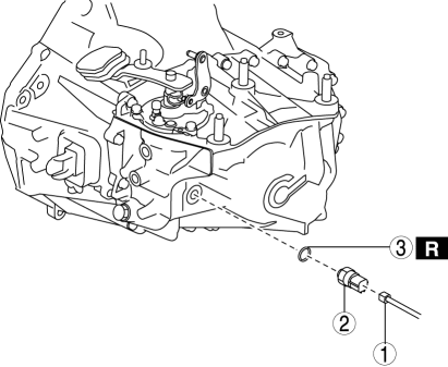
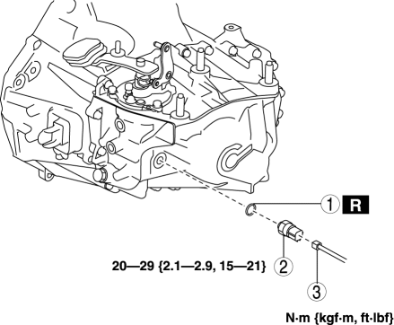
8. Remove the detent ball pin in the order shown in the figure
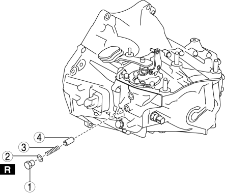
|
1 |
Plug |
|
2 |
Gasket |
|
3 |
Spring |
|
4 |
Detent ball pin |
9. Remove the back-up light switch in the order shown in the figure
|
1 |
Connector |
|
2 |
Back-up light switch |
|
3 |
Gasket |
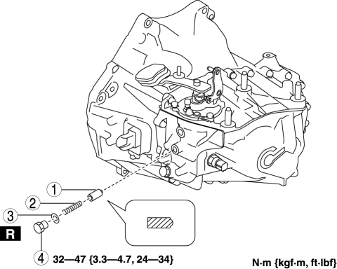
10. Remove the shift control module in the order shown in the figure
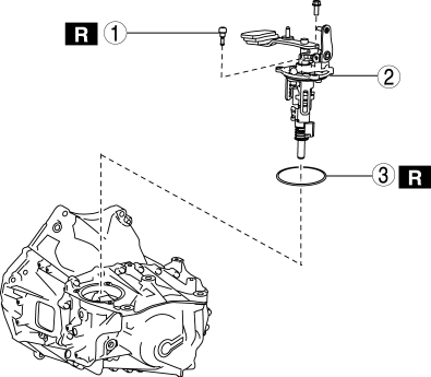
|
1 |
Breather |
|
2 |
Shift control module |
|
3 |
O-ring |
Installation
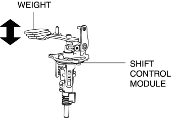
1. Verify that the shift control module is in the neutral position.
NOTE:
-
If the shift control module is in the neutral position, the shift lever with the weight can be moved up and down to a large extent.
2. Install the shift control module in the order shown in the figure
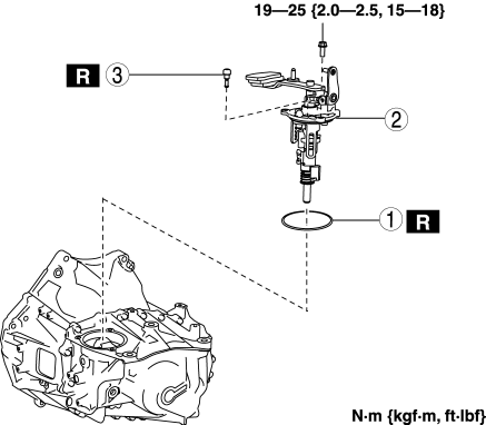
|
1 |
O-ring |
|
2 |
Shift control module |
|
3 |
Breather |
3. Install the back-up light switch in the order shown in the figure
|
1 |
Gasket |
|
2 |
Back-up light switch |
|
3 |
Connector |
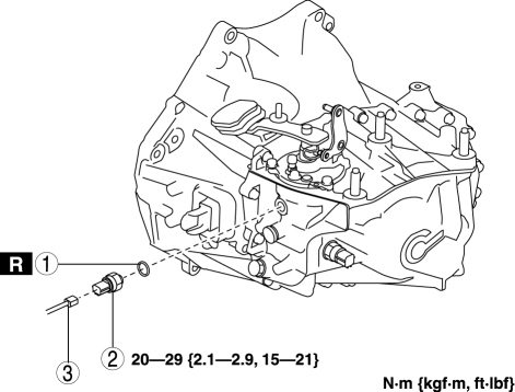
4. Install the detent ball pin in the order shown in the figure
|
1 |
Detent ball pin |
|
2 |
Spring |
|
3 |
Gasket |
|
4 |
Plug |
5. Install the neutral switch in the order shown in the figure
|
1 |
Gasket |
|
2 |
Neutral switch |
|
3 |
Connector |
6. Connect the control cable to the transaxle.
7. Make sure that the shift lever can be shifted smoothly.
8. Install the battery tray and battery..
9. Install the air cleaner and air hose as a single unit..
10. Connect the negative battery cable..
11. Install the plug hole plate..
 Shift And Select Mechanism [C66 M R]
Purpose, Function
The shift and select mechanism moves the shift fork to change gears according
to the operation of the shift lever in the cabin.
Construction
Shift control module ...
 Synchronizer Mechanism [C66 M R]
Purpose, Function
For smooth gear changes, the synchronizer mechanism synchronizes the rotation
of the engaging area and engages gears.
Construction
Detent ball-type synchronizer ...
Other materials:
Door Module Panel
Purpose, Function
Styrofoam door module panels have been adopted for reducing vehicle weight.
Construction
Styrofoam is applied to the door module panels (shaded areas) during manufacture.
...
Front Console Removal/Installation
CAUTION:
Affix protective tape to the position shown in the figure.
1. Disconnect the negative battery cable..
2. Remove the following parts:
a. Decoration panel.
b. Shift lever knob (MTX).
c. Front console box.
d. Shift panel.
e. Upper panel.
f. Rear console.
g. ...
Engine SST
1: Mazda SST number
2: Global SST number
Example
1:49 UN20 5072
2:205–072
Holder
1:–
2:AKS042808
Adapter
1: 49 UN20 5072
2: 205–072
Holder
1: 49 B011 105
2: –
...
