Mazda CX-5 Service & Repair Manual: Shift And Select Mechanism [C66 M R]
Purpose, Function
-
The shift and select mechanism moves the shift fork to change gears according to the operation of the shift lever in the cabin.
Construction
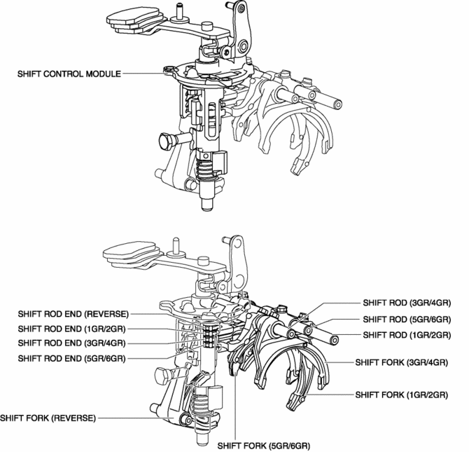
Shift control module
-
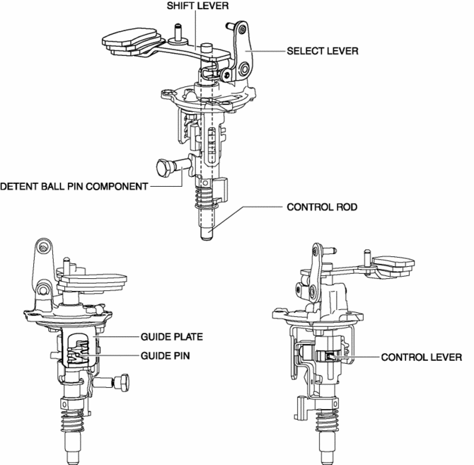
The moving parts of the shift control module are vertically positioned..
-
In this module, the control lever which moves the shift rod end is directly assembled to the control rod. In addition, because the control rod moves up and down, the weight of the control rod is utilized when the control rod moves down.
Slide ball bearing
-
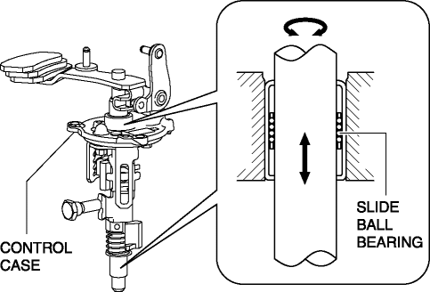
A slide ball bearing has been adopted to the sliding area between the control rod and the transaxle case, and between the control rod and the control case.
-
In this part, the bearing case moves in the drive and thrust directions.
-
Compared to the conventional bushing, sliding resistance between the control rod and the transaxle case, and between the control rod and the control case has been reduced.
Operation
NOTE:
-
Shifting operations from neutral to each gear are explained in this section.
1GR
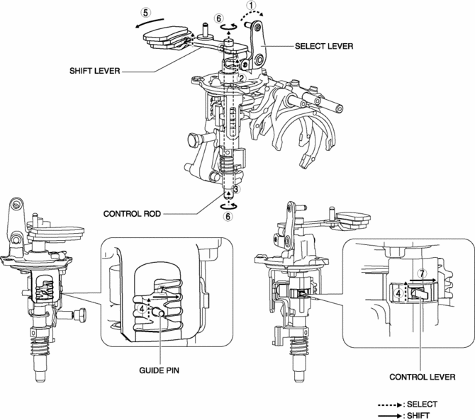
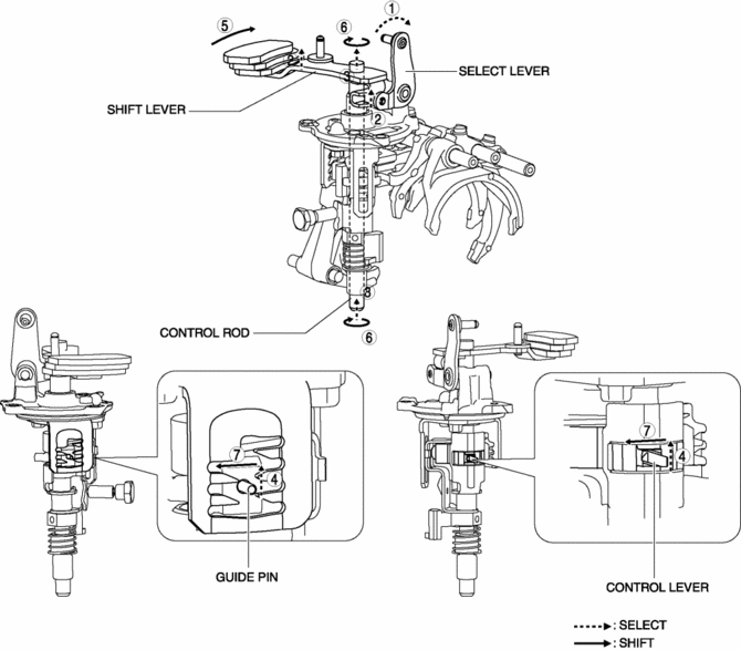
1. When the shift lever in the cabin is tilted to the left to shift to 1GR, the select lever moves in the direction of arrow 1 shown in the figure.
2. Following the movement of the select lever, the shift lever moves in the direction of arrow 2 shown in the figure.
3. Following the movement of the select lever, the shift lever moves in the direction of arrow 3 shown in the figure.
4. Following the movement of the select lever, the control lever and the guide pin move in the direction of arrow 4 shown in the figure.
5. When the shift lever in the cabin is tilted forward to shift to 1GR, the shift lever in the engine compartment moves in the direction of arrow 5 shown in the figure.
6. Following the movement of the shift lever in the engine compartment, the control rod moves in the direction of arrow 6 shown in the figure.
7. Following the movement of the shift lever in the engine compartment, the control lever and the guide pin move in the direction of arrow 7 shown in the figure.
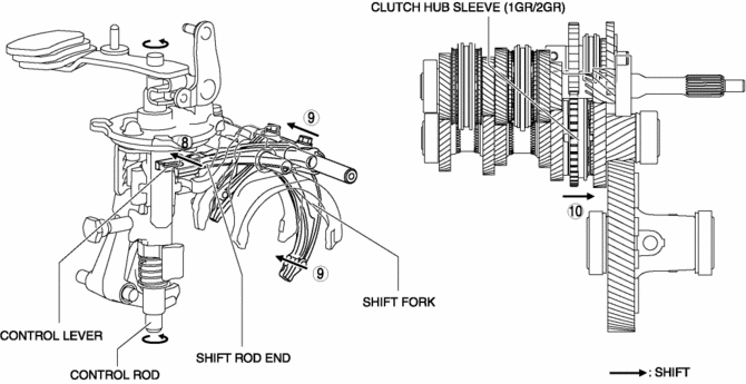
8. Because the control rod turns with the control lever, the control lever pushes the shift rod end and moves it in the direction of arrow 8 shown in the figure.
9. The shift rod end and the shift fork are integrated with the shift rod. Therefore, the movement of the shift rod end is transmitted to the shift fork via the shift rod, and the shift fork moves in the direction of arrow 9.
10. The shift fork moves the clutch hub sleeve in the direction of arrow 10 shown in the figure.
11. The shift change to 1GR is completed.
2GR
1. When the shift lever in the cabin is tilted to the left to shift to 2GR, the select lever moves in the direction of arrow 1 shown in the figure.
2. Following the movement of the select lever, the shift lever moves in the direction of arrow 2 shown in the figure.
3. Following the movement of the select lever, the shift lever moves in the direction of arrow 3 shown in the figure.
4. Following the movement of the select lever, the control lever and the guide pin move in the direction of arrow 4 shown in the figure.
5. When the shift lever in the cabin is tilted rearward to shift to 2GR, the shift lever in the engine compartment moves in the direction of arrow 5 shown in the figure.
6. Following the movement of the shift lever in the engine compartment, the control rod moves in the direction of arrow 6 shown in the figure.
7. Following the movement of the shift lever in the engine compartment, the control lever and the guide pin move in the direction of arrow 7 shown in the figure.
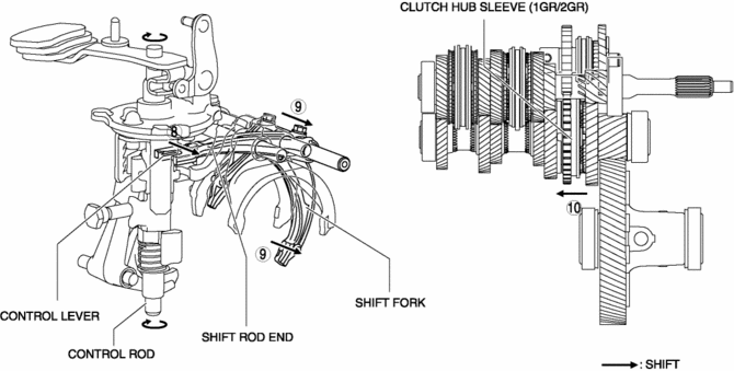
8. Because the control rod turns with the control lever, the control lever pushes the shift rod end and moves it in the direction of arrow 8 shown in the figure.
9. The shift rod end and the shift fork are integrated with the shift rod. Therefore, the movement of the shift rod end is transmitted to the shift fork via the shift rod, and the shift fork moves in the direction of arrow 9.
10. The shift fork moves the clutch hub sleeve in the direction of arrow 10 shown in the figure.
11. The shift change to 2GR is completed.
3GR
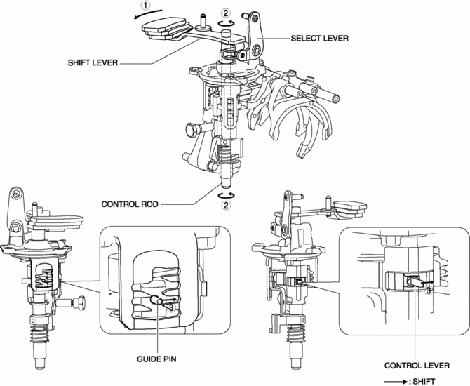
1. When the shift lever in the cabin is tilted forward to shift to 3GR, the shift lever in the engine compartment moves in the direction of arrow 1 shown in the figure.
2. Following the movement of the shift lever in the engine compartment, the control rod moves in the direction of arrow 2 shown in the figure.
3. Following the movement of the shift lever in the engine compartment, the control lever and the guide pin move in the direction of arrow 3 shown in the figure.
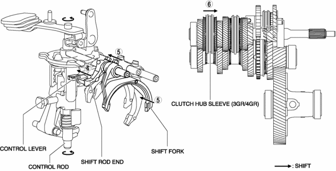
4. Because the control rod turns with the control lever, the control lever pushes the shift rod end and moves it in the direction of arrow 4 shown in the figure.
5. The shift rod end and the shift fork are integrated with the shift rod. Therefore, the movement of the shift rod end is transmitted to the shift fork via the shift rod, and the shift fork moves in the direction of arrow 5.
6. The shift fork moves the clutch hub sleeve in the direction of arrow 6 shown in the figure.
7. The shift change to 3GR is completed.
4GR
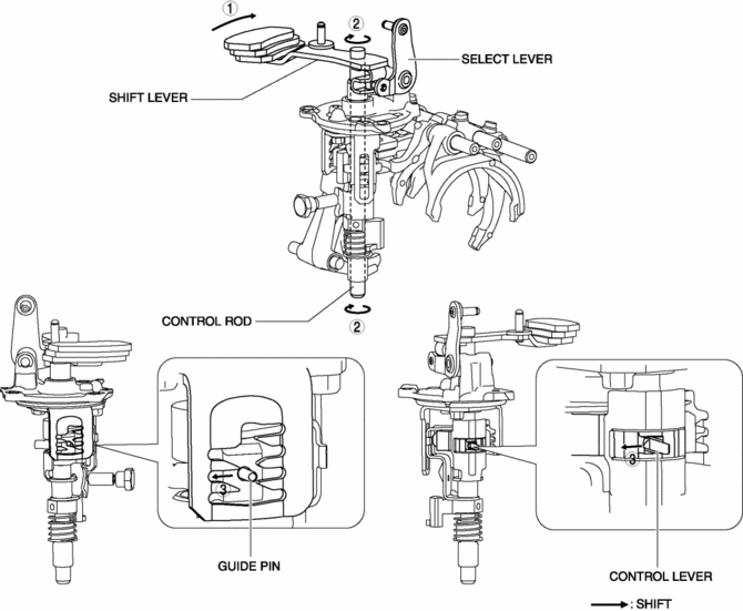
1. When the shift lever in the cabin is tilted rearward to shift to 4GR, the shift lever in the engine compartment moves in the direction of arrow 1 shown in the figure.
2. Following the movement of the shift lever in the engine compartment, the control rod moves in the direction of arrow 2 shown in the figure.
3. Following the movement of the shift lever in the engine compartment, the control lever and the guide pin move in the direction of arrow 3 shown in the figure.
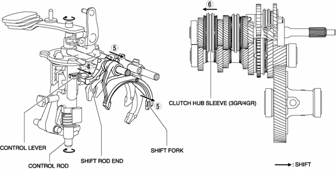
4. Because the control rod turns with the control lever, the control lever pushes the shift rod end and moves it in the direction of arrow 4 shown in the figure.
5. The shift rod end and the shift fork are integrated with the shift rod. Therefore, the movement of the shift rod end is transmitted to the shift fork via the shift rod, and the shift fork moves in the direction of arrow 5.
6. The shift fork moves the clutch hub sleeve in the direction of arrow 6 shown in the figure.
7. The shift change to 4GR is completed.
5GR
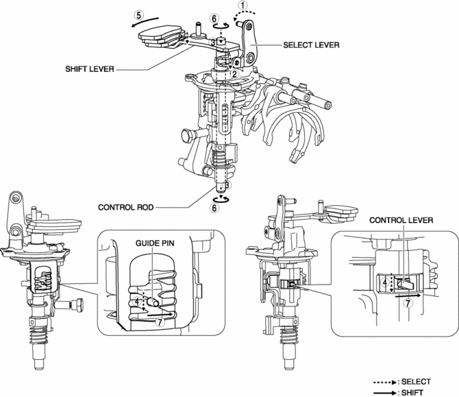
1. When the shift lever in the cabin is tilted to the right to shift to 5GR, the select lever moves in the direction of arrow 1 shown in the figure.
2. Following the movement of the select lever, the shift lever moves in the direction of arrow 2 shown in the figure.
3. Following the movement of the select lever, the shift lever moves in the direction of arrow 3 shown in the figure.
4. Following the movement of the select lever, the control lever and the guide pin move in the direction of arrow 4 shown in the figure.
5. When the shift lever in the cabin is tilted forward to shift to 5GR, the shift lever in the engine compartment moves in the direction of arrow 5 shown in the figure.
6. Following the movement of the shift lever in the engine compartment, the control rod moves in the direction of arrow 6 shown in the figure.
7. Following the movement of the shift lever in the engine compartment, the control lever and the guide pin move in the direction of arrow 7 shown in the figure.
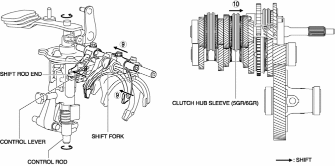
8. Because the control rod turns with the control lever, the control lever pushes the shift rod end and moves it in the direction of arrow 8 shown in the figure.
9. The shift rod end and the shift fork are integrated with the shift rod. Therefore, the movement of the shift rod end is transmitted to the shift fork via the shift rod, and the shift fork moves in the direction of arrow 9.
10. The shift fork moves the clutch hub sleeve in the direction of arrow 10 shown in the figure.
11. The shift change to 5GR is completed.
6GR
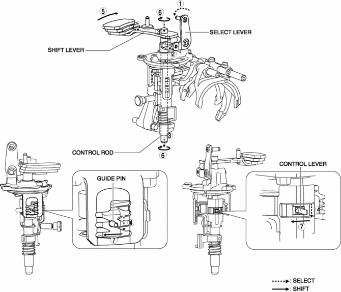
1. When the shift lever in the cabin is tilted to the right to shift to 6GR, the select lever moves in the direction of arrow 1 shown in the figure.
2. Following the movement of the select lever, the shift lever moves in the direction of arrow 2 shown in the figure.
3. Following the movement of the select lever, the shift lever moves in the direction of arrow 3 shown in the figure.
4. Following the movement of the select lever, the control lever and the guide pin move in the direction of arrow 4 shown in the figure.
5. When the shift lever in the cabin is tilted rearward to shift to 6GR, the shift lever in the engine compartment moves in the direction of arrow 5 shown in the figure.
6. Following the movement of the shift lever in the engine compartment, the control rod moves in the direction of arrow 6 shown in the figure.
7. Following the movement of the shift lever in the engine compartment, the control lever and the guide pin move in the direction of arrow 7 shown in the figure.
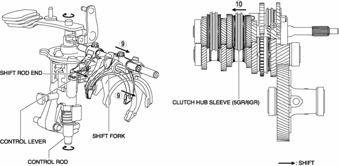
8. Because the control rod turns with the control lever, the control lever pushes the shift rod end and moves it in the direction of arrow 8 shown in the figure.
9. The shift rod end and the shift fork are integrated with the shift rod. Therefore, the movement of the shift rod end is transmitted to the shift fork via the shift rod, and the shift fork moves in the direction of arrow 9.
10. The shift fork moves the clutch hub sleeve in the direction of arrow 10 shown in the figure.
11. The shift change to 6GR is completed.
Reverse
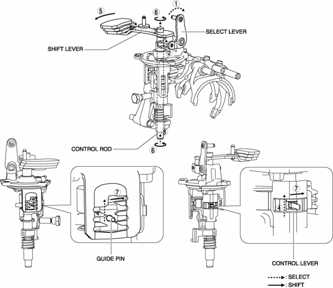
1. When the shift lever in the cabin is tilted to the left to shift to the reverse gear, the select lever moves in the direction of arrow 1 shown in the figure.
2. Following the movement of the select lever, the shift lever moves in the direction of arrow 2 shown in the figure.
3. Following the movement of the select lever, the shift lever moves in the direction of arrow 3 shown in the figure.
4. Following the movement of the select lever, the control lever and the guide pin move in the direction of arrow 4 shown in the figure.
5. When the shift lever in the cabin is tilted forward to shift to the reverse gear, the shift lever in the engine compartment moves in the direction of arrow 5 shown in the figure.
6. Following the movement of the shift lever in the engine compartment, the control rod moves in the direction of arrow 6 shown in the figure.
7. Following the movement of the shift lever in the engine compartment, the control lever and the guide pin move in the direction of arrow 7 shown in the figure.
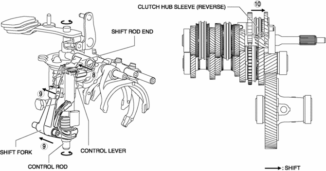
8. Because the control rod turns with the control lever, the control lever pushes the shift rod end and moves it in the direction of arrow 8 shown in the figure.
9. The shift rod end and the shift fork are integrated with the shift rod. Therefore, the movement of the shift rod end is transmitted to the shift fork via the shift rod, and the shift fork moves in the direction of arrow 9.
10. The shift fork moves the clutch hub sleeve in the direction of arrow 10 shown in the figure.
11. The shift change to the reverse gear is completed.
 Powertrain System [C66 M R]
Purpose, Function
The powertrain mechanism changes the gear combination by engaging or releasing
the clutch hub and gear, and changes the power transmission route. Because of
the change i ...
 Shift Control Module Removal/Installation [C66 M R]
Removal
1. Shift the shift lever to the neutral position.
2. Remove the plug hole plate..
3. Disconnect the negative battery cable..
4. Remove the air cleaner and air hose as a single unit..
...
Other materials:
Side Air Bag Module Removal/Installation [Standard Deployment Control System]
WARNING:
Handling the air bag module improperly can accidentally operate (deploy)
the air bag module, which may seriously injure you. Read the air bag system
service warnings and cautions before handling the air bag module..
If the side air bag module is installed with debris i ...
Room Straight Line Dimensions (1) [Dimensions]
Point symbol
Designation
Hole diameter or bolt or nut size mm {in}
A
Front pillar inner datum hole
?7 {0.3}
B
Front pillar inner datum hole
?7 {0.3}
C
...
Keyless Antenna [Advanced Keyless Entry System]
Purpose
Outputs a request signal and specifies the remote transmitter location.
Function
The keyless antenna outputs request signals to the inside and outside of
the vehicle based on the signals from the LF control unit.
Construction, Operation
The antennas for re ...
