Mazda CX-5 Service & Repair Manual: Relay Inspection
Relay Type
|
Connector type |
Part name |
|
Type A |
|
|
Type B |
|
|
Type C |
Blower relay |
|
Type D |
|
|
Type E |
Starter relay |
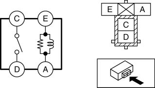
Type A
1. Remove the relay..
2. Verify the continuity between relay terminals E and A.
-
If it can be verified, go to the next step.
-
If it cannot be verified, replace the relay..
3. Apply battery voltage to relay terminal E, and connect terminal A to ground.
4. Verify the continuity between relay terminals C and D.
-
If it cannot be verified, replace the relay..
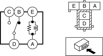
Type B
1. Remove the relay..
2. Verify the continuity between relay terminals E and A.
-
If it can be verified, go to the next step.
-
If it cannot be verified, replace the relay..
3. Verify the continuity between the relay terminals B and D.
-
If it can be verified, go to the next step.
-
If it cannot be verified, replace the relay..
4. Apply battery voltage to relay terminal E, and connect terminal A to ground.
5. Verify the continuity between relay terminals C and D.
-
If it cannot be verified, replace the relay..
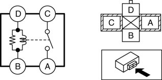
Type C
1. Remove the relay..
2. Verify the continuity between the relay terminals D and B.
-
If it can be verified, go to the next step.
-
If it cannot be verified, replace the relay..
3. Apply battery voltage to relay terminal D, and connect terminal B to ground.
4. Verify the continuity between relay terminals C and A.
-
If it cannot be verified, replace the relay..
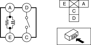
Type D
1. Remove the relay..
2. Verify the continuity between relay terminals A and E.
-
If it can be verified, go to the next step.
-
If it cannot be verified, replace the relay..
3. Apply battery voltage to relay terminal A, and connect terminal E to ground.
4. Verify the continuity between relay terminals D and C.
-
If it cannot be verified, replace the relay..
Type E
1. Remove the relay..
2. Verify the continuity between relay terminals A and E.

-
If it can be verified, go to the next step.
-
If it cannot be verified, replace the relay..
3. Apply battery voltage to relay terminal A, and connect terminal E to ground.
4. Verify the continuity between relay terminals C and D.
-
If it cannot be verified, replace the relay..
 Main Relay [Skyactiv G 2.0]
Purpose/Function
Supplies power to each part.
Supplies battery voltage to each part based on the signals from the PCM even
though the ignition is switched on or off.
Constructi ...

Other materials:
Liftgate Side Trim Removal/Installation
1. Remove the liftgate upper trim..
2. Remove the fastener A.
3. Take the shaded area shown in the figure, and pull the liftgate side trim
in the direction of the arrow (1) while detaching clips B.
4. Take the shaded area shown in the figure, detach tabs C while pulling the
liftgate si ...
Front Fender Panel Removal/Installation
1. Disconnect the negative battery cable..
2. Remove the following parts:
a. Front bumper.
b. Front combination light.
c. Front bumper slider.
d. Front over fender.
3. Remove bolts A and fasteners B.
4. Remove bolts C.
5. Remove the front fender panel.
6. Install in the reverse ...
Magnet Clutch [Manual Air Conditioner]
Purpose
The magnetic clutch transmits the rotation force from the engine to the shaft
in the A/C compressor.
Function
The magnetic clutch engages or disengages the magnetic clutch and the A/C
turns on or off by switching the power transmission from the engine.
Con ...
