Mazda CX-5 Service & Repair Manual: Refrigerant Pressure Sensor Inspection [Manual Air Conditioner]
1. Install the manifold gauge.
2. Verify the high-pressure side reading of the manifold gauge.
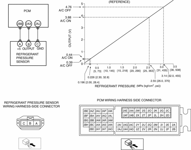
3. Measure the terminal voltage at PCM terminals 2BB, 2AX and 2AJ
4. Using the graph below, measure and verify the terminal voltage at 2AX.
5. Follow the PCM inspection when measuring the other terminal voltages..
-
Terminal 2BB: Approx. 5 V (Ignition switch on)
-
Terminal 2AJ: 1.0 V or less
-
If the each voltage is not normal, inspect the related wiring harness.
-
If there is any malfunction, replace the related wiring harness.
-
If wiring harness is normal, replace the refrigerant pressure sensor.

 Refrigerant Pressure Sensor Inspection [Full Auto Air Conditioner]
1. Install the manifold gauge.
2. Verify the high-pressure side reading of the manifold gauge.
3. Measure the terminal voltage at PCM terminal 2BB, 2AX and 2AJ
4. Using the graph below, measure ...
 Refrigerant Pressure Sensor Removal/Installation [Full Auto Air Conditioner]
1. Disconnect the negative battery cable..
2. Discharge the refrigerant..
3. Disconnect the refrigerant pressure sensor connector.
CAUTION:
If moisture or foreign material enters the ref ...
Other materials:
Ultra High Tension Steel [Construction]
Characteristics of Ultra High-Tensile Steel Plates
Ultra high-tensile steel plates have enhanced tensile strength compared to
previous high-tensile steel plates.
Because the strength is maintained even though the plates are thin-walled,
the ultra high-tensile steel plates ar ...
Remote Transmitter Battery Voltage Inspection
NOTE:
Because the remote transmitter battery power cannot be determined using the
battery itself, determine by the remote transmitter battery low warning operation
conditions.
Operation procedure for remote transmitter battery low warning
1. Place the remote transmitter inside t ...
Automatic Transaxle Fluid (ATF) Adjustment [Fw6 A EL, Fw6 Ax EL]
CAUTION:
Only adjust the ATF level when the ATF temperature is 45—55 °C {113—131 °F}.
If the ATF level is incorrect, it could damage the transaxle.
Do not add ATF over the specification. Otherwise, the transaxle performance
could be reduced and ATF could leak.
1. Re ...
