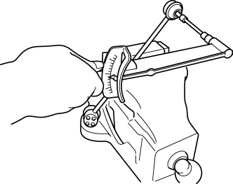
Mazda CX-5 Service & Repair Manual: Rear Stabilizer Control Link Inspection
1. Remove the rear stabilizer control link..
2. Inspect for bending or damage. If there is any malfunction, replace the rear stabilizer control link.
3. Rotate the ball joint stud 10 times
and shake it side to side 10 times
.
4. Measure the ball-joint rotational torque using an Allen wrench and a torque wrench.

-
Rear stabilizer control link ball joint starting torque
-
0.8—3.5 N·m {8.2—35 kgf·cm, 7.1—30 in·lbf}
-
If not within the specification, replace the rear stabilizer control link.
-
Even when within the specification, if there is excessive play in the ball joint, replace the rear stabilizer control link.
 Rear Shock Absorber Removal/Installation
1. Remove in the order indicated in the table.
2. Install in the reverse order of removal.
1
Rear shock absorber upper nut
(See Rear Shock Absorber Upper nut Install ...
 Rear Stabilizer Removal/Installation [2 Wd]
WARNING:
Verify that the rear crossmember is securely supported by a jack. If the
rear crossmember falls off, it can cause serious injury or death, and damage
to the vehicle.
C ...
Other materials:
Rear Trailing Link Removal/Installation
1. Remove the floor under cover..
2. Disconnect the rear parking cable..
3. Remove in the order indicated in the table.
4. Install in the reverse order of removal.
5. Inspect the wheel alignment and adjust it if necessary..
1
Rear trailing link installatio ...
Front Pillar Installation [Panel Replacement]
Symbol Mark
Installation Procedure
1. When installing new parts, measure and adjust the body as necessary to conform
with standard dimensions.
2. Drill holes for the plug welding before installing the new parts.
3. After temporarily installing new parts, make sure the related parts fit p ...
Trip Computer Information System
Outline
The trip computer system displays the instantaneous fuel economy, average
fuel economy, remaining distance to empty, and the average vehicle speed.
The instrument cluster performs trip computer system fail-safe..
Function
The instrument cluster controls the tri ...
