
Mazda CX-5 Service & Repair Manual: Rear Seat Back Removal/Installation
CAUTION:
-
When removing or putting in the rear seat, contact with the surrounding areas of the vehicle could cause scratches and damage. When removing or putting in the rear seat, always use two or more persons to perform the work and be careful not to scratch or damage the rear seat and the surrounding area of the vehicle.
-
When performing the procedure with a rear seat back removed from the vehicle, perform the procedure on a clean cloth so as not to damage or soil the seat.
NOTE:
-
When removing the rear seat back from the vehicle or putting it back in, it can be performed smoothly by removing the headrest.
6:4 Split Type
1. Remove the trunk board..
2. Press the push knob to fold the rear seat back.
3. Remove bolts A.
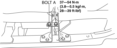
4. Remove the plate in the direction of the arrow (1) shown in the figure.

5. Remove bolts B.
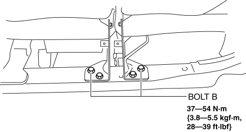
6. Remove bolts C.
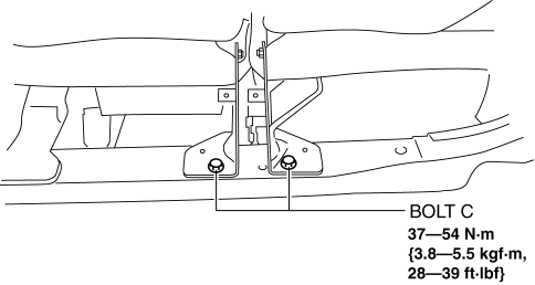
7. Remove bolt D.
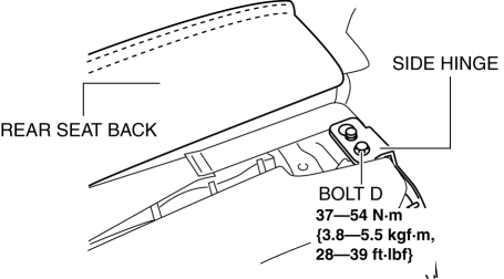
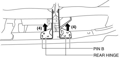
8. After moving the rear seat in the direction of the arrow (2) shown in the figure, remove pin B while moving the side hinge in the direction of the arrow (3).

9. Move the rear hinge in the direction of the arrow (4) shown in the figure and set pin A aside.
10. Remove the rear seat back.
4:2:4 Split Type
1. Remove the trunk board..
2. Remove the rear seat..
3. Remove bolts A.
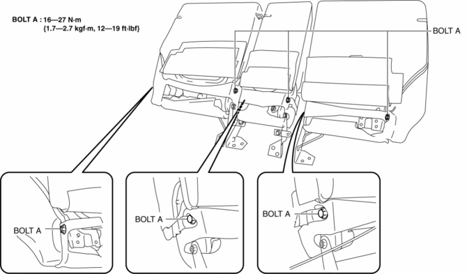
4. Remove the rear seat back.
5. Install in the reverse order of removal.
 Rear Seat Back Frame Removal/Installation
CAUTION:
When performing the procedure with a rear seat removed from the vehicle,
perform the procedure on a clean cloth so as not to damage or soil the seat.
6:4 Split Type
1. Remov ...
 Rear Seat Back Striker Removal/Installation
1. Disconnect the negative battery cable..
2. Press the push knob to fold the rear seat back.
3. Remove the following parts:
a. Trunk board.
b. Trunk end trim.
c. Rear scuff plate.
d. Trun ...
Other materials:
Awd Control Module Removal/Installation
CAUTION:
When performing configuration, it is necessary to read the coupling component
calibration data from the AWD control module before replacing it. Connect the
M-MDS to the vehicle and perform vehicle identification before removing the
AWD control module. The coupling component ...
Outside the United States/Canada
Government regulations in the United States/Canada require that automobiles meet
specific emission regulations and safety standards. Therefore, vehicles built for
use in the United States/Canada may differ from those sold in other countries.
The differences may make it difficult or even impossi ...
Antilock Brake System (ABS)
The ABS control unit continuously monitors the speed of each wheel. If one wheel
is about to lock up, the ABS responds by automatically releasing and reapplying
that wheel's brake.
The driver will feel a slight vibration in the brake pedal and may hear a chattering
noise from the brake sy ...
