Mazda CX-5 Service & Repair Manual: Rear Seat Back Frame Removal/Installation
CAUTION:
-
When performing the procedure with a rear seat removed from the vehicle, perform the procedure on a clean cloth so as not to damage or soil the seat.
6:4 Split Type
1. Remove the trunk board..
2. Remove the rear seat back..
3. Remove the headrest.
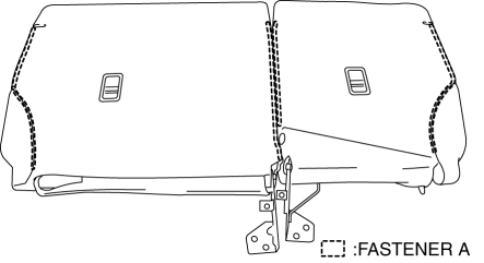
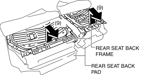
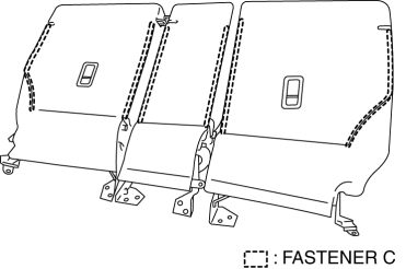
4. Open fasteners A.
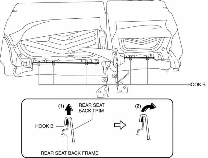
5. Slide hook B in the order of the arrows (1) and (2) shown in the figure, and set the rear seat back frames aside.
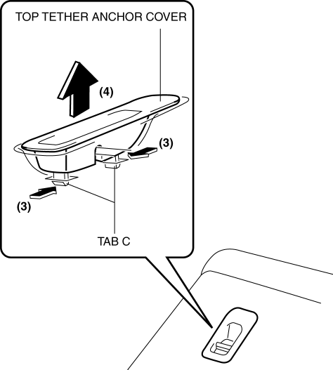
6. Release tabs C in the direction of the arrow (3) shown in the figure and remove the top tether anchor cover in the direction of the arrow (4).
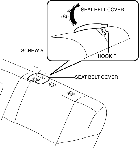
7. Remove screws A, and remove the seat belt cover in the direction of the arrow (5) shown in the figure while setting hooks D aside.

8. Remove screw B.
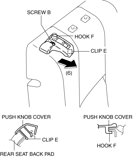
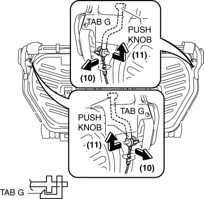
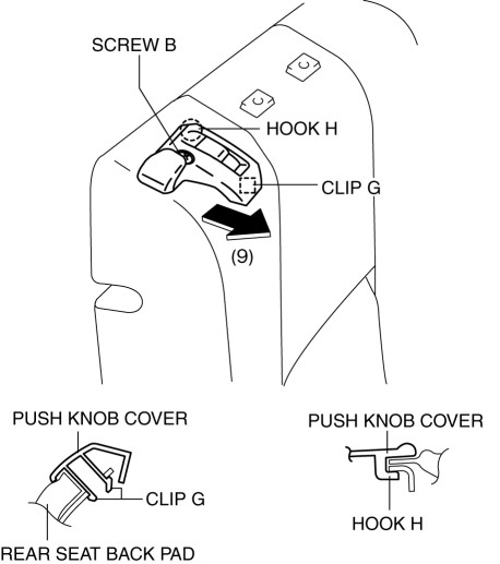
9. Remove clip E and remove the push knob cover in the direction of the arrow (6) shown in the figure while setting hook F aside.
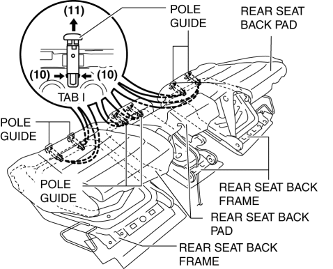
10. Peel back the rear seat back pad, and pull out the pole guide in the direction of the arrow (8) while releasing the tabs G in the direction of the arrow (7) shown in the figure.

11. Pull the rear seat back frame in the direction of the arrow (9) shown in the figure, and remove it from the rear set back pad.
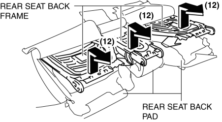
12. Remove tabs H in the direction of the arrow (10) shown in the figure and remove the push knob in the direction of the arrow (11).
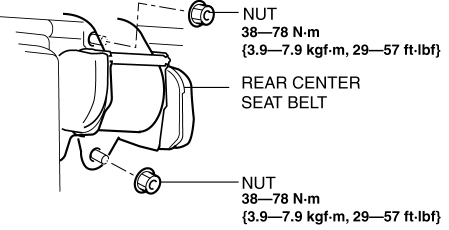
13. Remove nuts, and then remove the rear center seat belt.
14. Remove the clips I, and then remove the striker cover in the direction of the arrow (12) while setting hooks J aside.

15. Install in the reverse order of removal.
4:2:4 Split Type
1. Remove the rear seat center armrest..
2. Remove the rear seat..
3. Remove the rear seat back..
4. Remove the headrest.
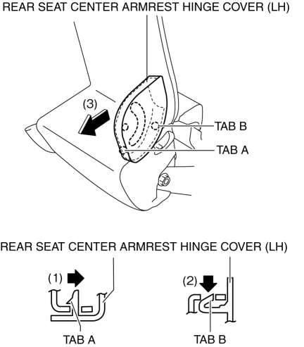
5. After releasing tab A in the direction of the arrow (1) shown in the figure, release tab B in the direction of the arrow (2) shown in the figure, and remove the rear seat center armrest hinge cover (LH) in the direction of the arrow (3).
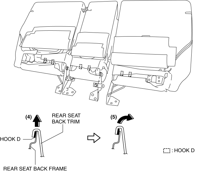
6. Open fasteners C.
7. Slide hooks D in the order of the arrows (4) and (5) shown in the figure, and set the rear seat back frames aside.
8. Release tabs E in the direction of the arrow (6) shown in the figure and remove the top tether anchor cover in the direction of the arrow (7).

9. Remove screws A, and remove the seat belt cover in the direction of the arrow (8) shown in the figure while setting hooks F aside.
10. Remove screw B.
11. Remove screw B, and clip G and remove the push knob cover in the direction of the arrow (9) shown in the figure while setting hook H aside.
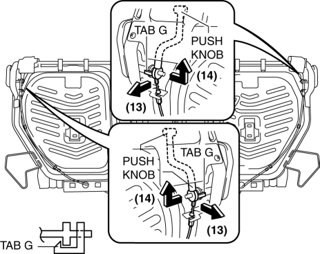
12. Partially peel back the seat back pad, release tabs I in the direction of the arrow (10) shown in the figure and pull out the pole guide in the direction of the arrow (11).
13. Pull the rear seat back frame in the direction of the arrow (12) shown in the figure, and remove it from the rear set back pad.
14. Remove tabs J in the direction of the arrow (13) shown in the figure and remove the push knob in the direction of the arrow (14).
15. Remove clips K.
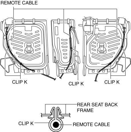
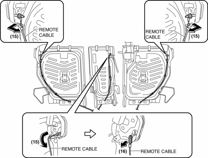
16. Remove the remote cable in the direction of the arrow (15) and (16) shown in the figure.
17. Remove screw C.
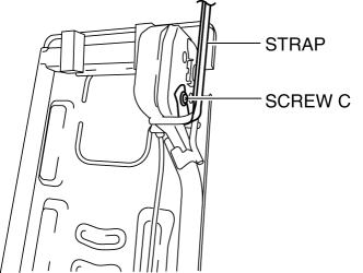
18. Remove the strap.
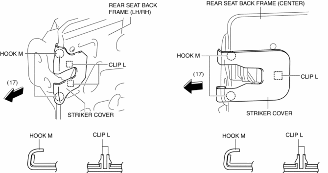
19. Remove the clips L, and then remove the striker cover in the direction of the arrow (17) while setting hooks M aside.
20. Remove nuts, and then remove the rear center seat belt.
21. Install in the reverse order of removal.
 Rear Seat
Purpose, Function
The following two types of rear seats have been adopted.
6:4 split-type seat
4:2:4 split-type seat
The following functions have been ado ...
 Rear Seat Back Removal/Installation
CAUTION:
When removing or putting in the rear seat, contact with the surrounding areas
of the vehicle could cause scratches and damage. When removing or putting in
the rear seat, always ...
Other materials:
Power Outer Mirror Switch Inspection
1. Disconnect the negative battery cable..
2. Remove the power outer mirror switch..
3. Verify that the continuity between the power outer mirror switch terminals
is as indicated in the table.
If not as indicated in the table, replace the power outer mirror switch..
...
DRL (Daytime Running Light) Bulb Removal/Installation
1. Disconnect the negative battery cable..
2. Disconnect the connector.
3. Rotate the DRL bulb in the direction of the arrow (1) shown in the figure
and remove it from the front combination light in the direction of the arrow (2)
shown in the figure.
4. Install in the reverse order ...
Rear Body Straight Line Dimensions (1) [Dimensions]
Point symbol
Designation
Hole diameter or bolt or nut size mm {in}
A
Liftgate hinge installation hole
?12 {0.47}
B
Liftgate stay damper installation hole
?10 {0.39}
...
