Mazda CX-5 Service & Repair Manual: Rear Mount Camera Inspection
1. Disconnect the negative battery cable..
2. Remove the following parts:
a. Liftgate upper trim.
b. Liftgate side trim.
c. Liftgate lower trim.
d. Liftgate garnish.
e. Rear mount camera.
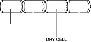
3. Prepare four dry cell batteries (1.5 V)
4. Connect the four dry cell batteries in a series.

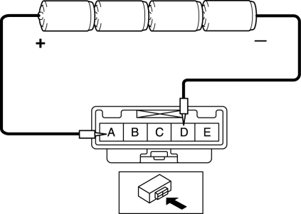
5. Connect the positive pole of the dry cell battery to rear mount camera terminal A, and the negative pole to terminal D.

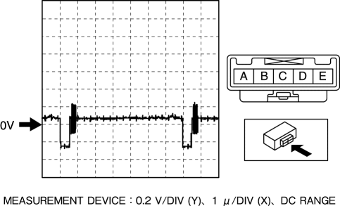
6. With the cell batteries being connected, measure the waveform between rear mount camera terminal C and body ground.
7. Verify that the waveform is displayed as shown in the figure.

8. If the voltage is not as shown in the figure, replace the rear mount camera.
 Rear Mount Camera
Purpose, Function
The rear mount camera shoots the conditions at the rear of the vehicle in
color, and after converting the video signal, it outputs the signal to the audio
unit. (with co ...
 Rear Mount Camera Removal/Installation
CAUTION:
The audio unit communicates with the rear mount camera and records the presence/non-presence
of the rear mount camera when the ignition is switched to ACC or ON (engine
off or o ...
Other materials:
Filament Inspection
1. Switch the ignition ON (engine off).
2. Turn the rear window defroster switch on.
CAUTION:
Directly touching the rear window defroster filament with the lead of the
tester could damage it. Wrap aluminum foil around the end of the lead and inspect
the filament by touching it ...
Seat Belt Extender
If your seat belt is not long enough, even when fully extended, a seat belt extender
may be available to you at no charge from your Authorized Mazda Dealer.
This extender will be only for you and for the particular vehicle and seat. Even
if it plugs into other seat belts, it may not hold in the ...
Resistor Removal/Installation [Manual Air Conditioner]
NOTE:
When removing the resistor, perform the procedure in the posture shown in
the figure.
1. Disconnect the negative battery cable..
2. Remove the dashboard under cover..
3. Disconnect the connector.
4. Rotate the resistor (2) while pressing the tab (1).
5. R ...
