Mazda CX-5 Service & Repair Manual: Rear Combination Light Removal/Installation
NOTE:
-
Fogging or condensation on the inside of the rear combination lights may occur due to a natural phenomenon occurring as a result of a temperature difference between the interior and exterior of the combination lights. However, it has no effect on the light performance because the temperature inside the rear combination lights rises after illuminating the brake/taillight bulbs or a period of time has elapsed.
1. Disconnect the negative battery cable..
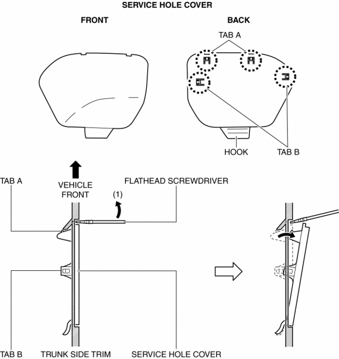
2. Insert a tape-wrapped flathead screwdriver into the service hole in the position shown in the figure.
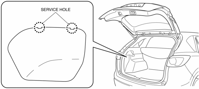
3. Move the flathead screwdriver in the direction of the arrow (1) shown in the figure, pull out the service hole cover, and detach the service hole cover tab and trunk side trim.
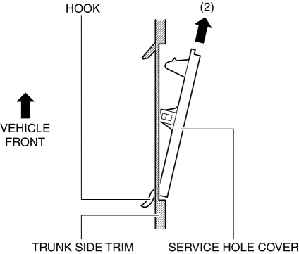
4. Pull out the service hole cover in the direction of the arrow (2) shown in the figure and pull out the service hole cover hook from the trunk side trim.
5. Remove the service hole cover.
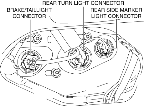
6. Disconnect the connectors.
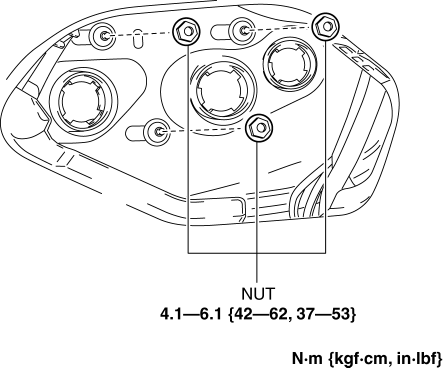
7. Remove the nuts.
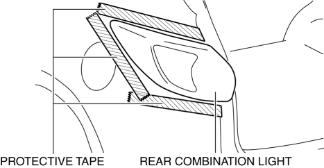
8. To prevent scratches or damage, affix protective tape to the position shown in the figure.
CAUTION:
-
When the rear combination light is removed from the body, perform the procedure after affixing protective tape to the body. Otherwise, the body could interfere with the rear combination light and cause scratching or damage to the body.
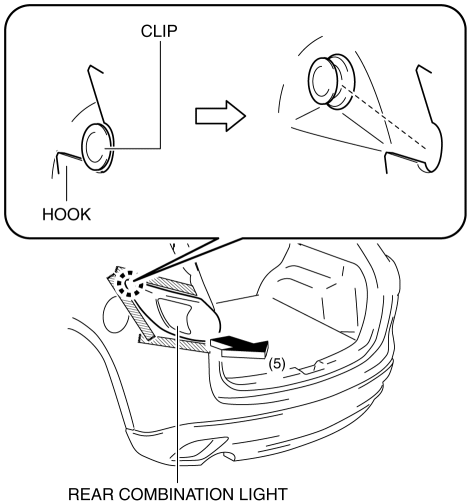
9. Pull the rear combination light in the direction of the arrow (5) shown in the figure and remove the rear combination light hook from the clip.
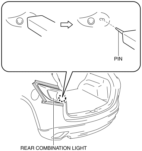
10. Pull out the rear combination light pin.
11. Remove the rear combination light.
12. Install in the reverse order of removal.
 Rear Combination Light
Purpose
The rear combination lights are used to signal the following conditions to
vehicles/people at the rear.
Rear turn lights: Signals a left or right turn of the vehicle.
...
 Rear Side Marker Light Bulb Removal/Installation
1. Disconnect the negative battery cable..
2. Insert a tape-wrapped flathead screwdriver into the service hole in the position
shown in the figure.
3. Move the flathead screwdriver in the di ...
Other materials:
Front Power Window Regulator Removal/Installation
1. Perform the front door glass preparation..
2. Disconnect the negative battery cable..
3. Remove the following parts:
a. Inner garnish.
b. Front door trim.
c. Front door glass.
d. Front door speaker.
e. Front power window motor.
4. Remove bolt A.
5. Remove nuts B.
6. Insert ...
Controller Area Network (Can) System
Outline
A CAN system has been adopted which can send and receive multiple signals
over a single communication path from related modules.
System wiring diagram
HS-CAN
MS-CAN
Structure
The CAN system consists of CAN system-related modules built into the CPU
...
Power Window Main Switch
Purpose
Remote control of door glass open/close and power outer mirror adjustment
are possible with occupant seated in the cabin.
Function
Power window main switch
Manual
When the power window main switch is operated for manual open/close operation,
it sends ...
