Mazda CX-5 Service & Repair Manual: Rear Accessory Socket Removal/Installation
1. Disconnect the negative battery cable..
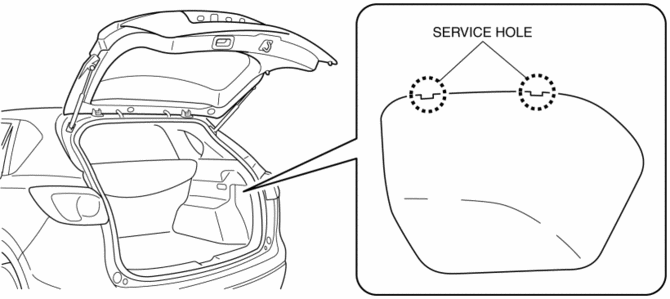
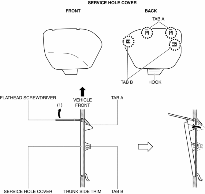
2. Insert a tape-wrapped flathead screwdriver into the service hole in the position shown in the figure.
3. Move the flathead screwdriver in the direction of the arrow (1) shown in the figure, pull out the service hole cover, and detach the service hole cover tab and trunk side trim.
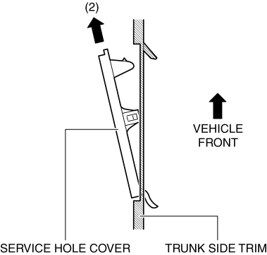
4. Pull out the service hole cover in the direction of the arrow (2) shown in the figure and pull out the service hole cover hook from the trunk side trim.
5. Remove the service hole cover.
6. Disconnect the connector.

7. Insert a tape-wrapped flathead screwdriver into the service hole in the position shown in the figure.

8. While pressing the cap tab in the direction of arrow (3) shown in the figure, push out the rear accessory socket in the direction of arrow (4) to detach the cap tab from the socket.
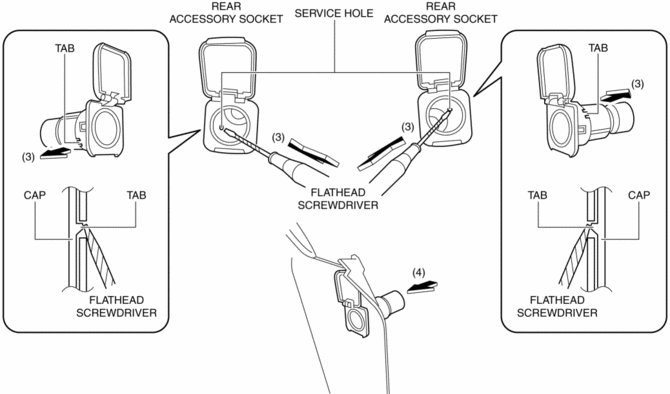
9. Pull the rear accessory socket in the direction of the arrow shown in the figure and remove it.

10. While pressing the cap tab in the direction of the arrow (5) shown in the figure, push out the cap in the direction of the arrow (6) shown in the figure to detach the cap tab from the trunk side trim.
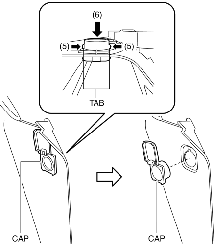
11. Remove the cap.
12. Install in the reverse order of removal.
 Rear Accessory Socket Inspection
1. Remove the rear accessory socket..
2. Connect the tester probe to the position shown in the figure and verify that
there is continuity.
If it cannot be verified, replace the rear ac ...
 Safety Systems
...
Other materials:
Door Ajar Warning Light
Purpose
The door-ajar warning light notifies the driver that any door or the liftgate
is open.
Function
When the instrument cluster receives any of the following signals sent from
the rear body control module (RBCM) via the CAN signal, the door-ajar warning
light illumin ...
Front Console Removal/Installation
CAUTION:
Affix protective tape to the position shown in the figure.
1. Disconnect the negative battery cable..
2. Remove the following parts:
a. Decoration panel.
b. Shift lever knob (MTX).
c. Front console box.
d. Shift panel.
e. Upper panel.
f. Rear console.
g. ...
Front Door Speaker Inspection
1. Disconnect the negative battery cable..
2. Remove the following parts:
a. Inner garnish.
b. Front door trim.
3. Disconnect the front door speaker connector..
4. Verify that the resistance and continuity between the front door speaker terminals
is as indicated in the table.
...
