Mazda CX-5 Service & Repair Manual: Pre Tensioner Seat Belt [Standard Deployment Control System]
Purpose
-
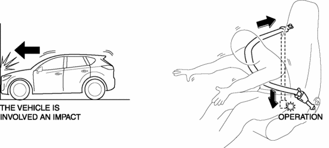
The pre-tensioner seat belt retracts and tightens the seat belt webbing to protect the front passengers during a collision.
Function
-
The pre-tensioner seat belts operate (deploy) based on the operation signal from the SAS control module to instantly retract and tighten the belt webbing, restraining the driver and front passenger.
Construction
-
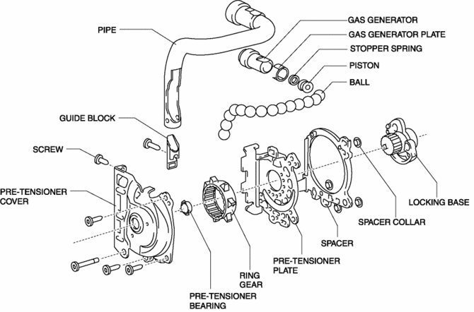
The pre-tensioner seat belt is installed to the front seat belt retractor.
-
The pre-tensioner seat belt consists of the following parts shown in the figure:
Operation
Normal operation (pre-tensioner non-operation)
-
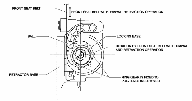
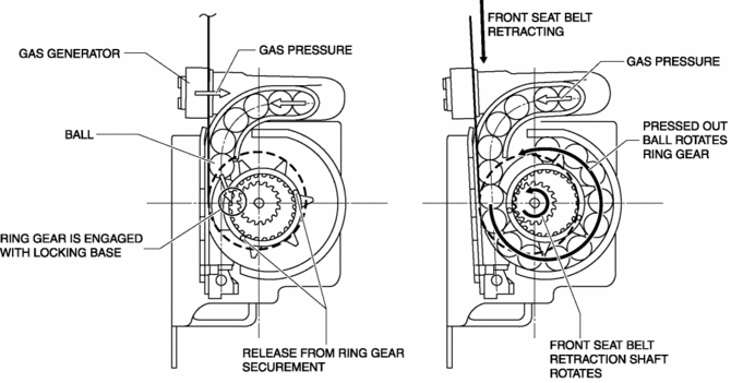
Normally, there is a gap between the locking base and the ring gear.
-
The ring gear rotates in conjunction with the withdrawal and retraction of the front seat belts, however, in the pre-tensioner part it is kept separated.
Pre-tensioner activation
1. The gas generator produces gas when it receives an operation signal from the SAS control module.
2. The ball in the cylinder is pressed by the gas pressure and the ring gear is removed from its securement.
3. The ring gear is engaged with the locking base and the force of the ball being pressed out is transmitted to the retraction shaft.
4. The front seat belt is retracted in conjunction with the rotation of the retraction shaft.
Fail-safe
-
Function not equipped.
 Passenger Side Air Bag Module [Two Step Deployment Control System]
Purpose
When the passenger-side air bag module receives an impact from a frontal
or frontal offset collision, the operation (deployment) of the air bag mediates
the impact to the head and ...
 Pre Tensioner Seat Belt [Two Step Deployment Control System]
Purpose
The pre-tensioner seat belt retracts and tightens the seat belt webbing to
protect the front passengers during a collision.
Function
The pre-tensioner seat belts operate ...
Other materials:
Upper Panel Removal/Installation
1. Disconnect the negative battery cable..
2. Remove the following parts:
a. Front console box.
b. Shift lever knob (MTX).
c. Shift panel.
3. Open the console lid.
4. Remove the button, then open the fastener.
5. Take the shaded area shown in the figure, and remove the upper panel ...
Engine Disassembly/Assembly
CAUTION:
When the transaxle is installed, do not suspend the engine. Otherwise, the
SST installation area of the cylinder head may be damaged due to excess weight.
Only suspend the engine after separating the engine and transaxle.
Applying excessive force (force of 100 N {10.2 ...
Filament Inspection
1. Switch the ignition ON (engine off).
2. Turn the rear window defroster switch on.
CAUTION:
Directly touching the rear window defroster filament with the lead of the
tester could damage it. Wrap aluminum foil around the end of the lead and inspect
the filament by touching it ...
