
Mazda CX-5 Service & Repair Manual: Panel Light Control Indicator Alarm
Purpose
-
The panel light control indicator alarm notifies the driver that the panel light brightness is either at maximum or minimum.
Function
-
If the panel light control switch is in the maximum rotation position right or left when the TNS switch ON signal (TNS and headlights illuminate) sent from the start stop unit via the CAN signal is received, the instrument cluster sounds the panel light control indicator alarm.
-
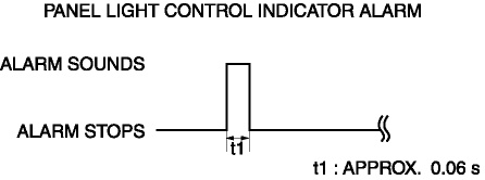
The panel light control indicator alarm sound pattern is as shown in the figure.
Construction
-
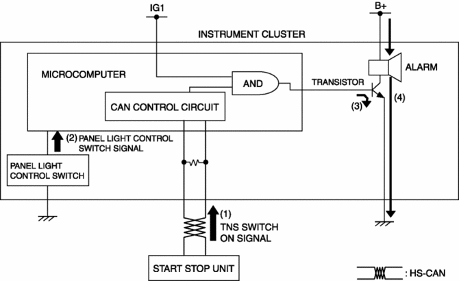
The panel light control indicator alarm sounds using the buzzer built into the instrument cluster.
Operation
1. The instrument cluster receives (1) the TNS switch ON signal from the start stop unit.
2. If the maximum rotation position of the panel light control switch is detected (2) when the TNS switch ON signal is received, the instrument cluster microcomputer turns on (3) the transistor.
3. When the transistor turns on, a ground circuit with the alarm is established and the alarm sounds (4).
Fail-safe
-
Function not equipped.
 Master Warning Light
Purpose
The master warning light warns the driver that any of the following malfunctions
is occurring.
Brake switch malfunction
Engine oil solenoid valve malfunction
...
 Power Steering Malfunction Indicator Light
Purpose
The power steering malfunction indicator light warns the driver that there
is a malfunction with the electric power steering (EPS) system.
Function
If there is a malfunc ...
Other materials:
Tcs/DSC Indicator Light
Purpose/Function
The TCS/DSC indicator light, built into the instrument cluster, informs the
driver of the following vehicle conditions.
TCS is operating. (Drive wheel is slipping.)
DSC is operating. (Vehicle side-slip condition.)
Roll over mitigation (RO ...
Ignition Coil/Ion Sensor Removal/Installation [Skyactiv G 2.0]
1. Disconnect the negative battery cable..
2. Remove the plug hole plate..
3. Remove in the order indicated in the table.
4. Install in the reverse order of removal.
1
Connector
2
Ignition coil
...
Blind Spot Monitoring (Bsm) Control Module
Purpose
Controls the blind spot monitoring (BSM) system.
Function
The BSM control module emits microwaves to detect an oncoming vehicle's position
and speed information via the reflected microwaves.
The BSM system is controlled based on the detected vehicle positio ...
