Mazda CX-5 Service & Repair Manual: Panel Light
Purpose
-
The panel light adjusts the instrument cluster and steering switch illumination brightness.
Function
-
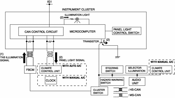
The instrument cluster adjusts the brightness of the following illumination lights when a TNS illumination signal sent via CAN transmission from the front body control module (FBCM) is received.
-
Instrument cluster
-
Climate control unit
-
Steering switch
-
Cluster switch
-
Hazard warning switch
-
Selector illumination
-
Audio unit
-
Clock (with manual A/C)
-
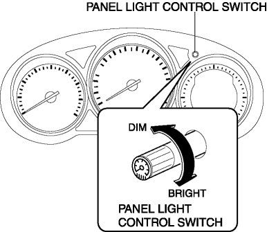
The instrument cluster changes the brightness of the illumination lights according to the rotation signal of the panel light control switch.
Construction
-
The panel light control switch is set in the instrument cluster.
Operation
-
When the ignition is switched ON (engine off or on), the instrument cluster receives (1) the TNS illumination signal from the front body control module (FBCM).
-
The instrument cluster performs the following controls when it receives the TNS illumination signal.
-
Changes the brightness of the instrument panel illumination.
-
Outputs a panel light signal via CAN signal to the climate control unit (with auto A/C)/clock (with manual A/C).
-
Turns on the panel light circuit transistor.
-
When the transistor turns on, a ground circuit with the panel light is established and the panel light illuminates.
Panel light control switch operation
-
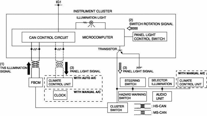
When the ignition is switched ON (engine off or on), the instrument cluster receives (1) the TNS illumination signal from the front body control module (FBCM).
-
The instrument cluster changes the brightness of the panel light according to the rotation angle when it receives a panel light control switch rotation signal while receiving the TNS illumination signal.
-
The instrument cluster outputs a panel light signal to related units.
Fail-safe
-
Function not equipped.
 PID/Data Monitor Inspection [Instrument Cluster]
1. Connect the M-MDS to the DLC-2.
2. After the vehicle is identified, select the following items from the initialization
screen of the M-MDS.
a. Select ŌĆ£DataLoggerŌĆØ.
b. Select ŌĆ£ModulesŌ ...
 Gauges
...
Other materials:
PID/Data Monitor Inspection [Start Stop Unit]
1. Connect the M-MDS to the DLC?2.
2. After the vehicle is identified, select the following items from the initialization
screen of the M-MDS.
Select ŌĆ£DataLoggerŌĆØ.
Select ŌĆ£ModulesŌĆØ.
Select ŌĆ£SSUŌĆØ.
3. Select the applicable PID from the PID table.
4. Veri ...
High Pressure Fuel Pump Removal/Installation
WARNING:
Fuel is very flammable liquid. If fuel spills or leaks from the pressurized
fuel system, it will cause serious injury or death and facility breakage. Fuel
can also irritate skin and eyes. To prevent this, always complete the ŌĆ£Fuel
Line Safety ProcedureŌĆØ, while referring ...
Meters and Gauges
1 Speedometer
2 Odometer, Trip Meter and Trip Meter Selector
3 Tachometer
4 Fuel Gauge
5 Dashboard Illumination
6 Outside Temperature Display
7 Trip Computer and INFO Switch
Speedometer
The speedometer indicates the speed of the vehicle.
Odometer, Trip Meter and Trip Meter Selector
...
