Mazda CX-5 Service & Repair Manual: Master Warning Light
Purpose
-
The master warning light warns the driver that any of the following malfunctions is occurring.
-
Brake switch malfunction
-
Engine oil solenoid valve malfunction
-
Automatic configuration malfunction
Function
-
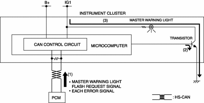
The instrument cluster illuminates the master warning light based on the following CAN signals:
-
Brake switch No.1 error signal, brake switch No.2 error signal, engine oil solenoid valve error signal, and automatic configuration error signal sent from the PCM
-
The instrument cluster flashes the master warning light based on the master warning light flash request signal sent from the PCM as a CAN signal.
-
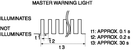
The master warning light flashing pattern is as indicated in the figure.
Construction
-
The instrument cluster microcomputer controls the illumination/flashing/turning off of the master warning light based on each error signal sent from the PCM.
-
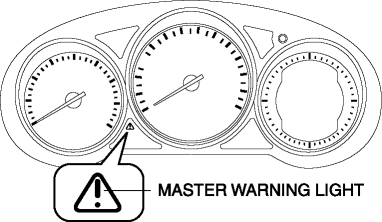
The master warning light is set in the instrument cluster.
Operation
-
When the ignition is switched ON (engine off or on), the instrument cluster receives (1) each error signal or a master warning light flash request signal from the PCM.
-
The instrument cluster turns the transistor on (2) intermittently for flashing and continuously for illumination based on each signal.
-
The master warning light flashes (3) when the transistor is turned on intermittently, and it illuminates (3) when the transistor is turned on continuously.
Fail-safe
-
Function not equipped.
 Low Fuel Warning Light
Purpose
The low fuel warning light warns the driver that the remaining fuel level
is low.
Function
The instrument cluster calculates the fuel quantity based on the following
...
 Panel Light Control Indicator Alarm
Purpose
The panel light control indicator alarm notifies the driver that the panel
light brightness is either at maximum or minimum.
Function
If the panel light control switch i ...
Other materials:
Splash Shield Removal/Installation
Front
Front splash shield No.1
1. Set the mudguard aside..
2. Remove fasteners A.
3. Remove the front splash shield No.1.
4. Install in the reverse order of removal.
Front splash shield No.2
1. Remove screw B.
2. Remove fasteners C.
3. Remove the front splash shield No.2.
4. ...
Rear Door Quarter Glass Removal/Installation
1. Fully lower the rear door glass.
2. Disconnect the negative battery cable..
3. Remove the rear door trim..
4. Remove the rear door weather strip arrow (1) shown in the figure.
5. Remove the service hole cover No.1 arrow (2) shown in the figure.
CAUTION:
When removing service ...
Cruise Control
Cruise Control
With cruise control, you can set and automatically maintain any speed of more
than about 25 km/h (16 mph).
WARNING
Do not use the cruise control under the following conditions: Using the cruise
control under the following conditions is dangerous and could result in loss of
ve ...
