Mazda CX-5 Service & Repair Manual: Lower Panel Removal/Installation
Driver-side
1. Disconnect the negative battery cable..
2. Remove the following parts:
a. Driver-side front scuff plate.
b. Driver-side front side trim.
c. Switch panel.
d. Decoration panel.
e. Shift lever knob (MTX).
f. Front console box.
g. Shift panel.
h. Upper panel.
i. Rear console.
j. Side wall.
k. Front console.
l. Hood release lever.
3. Remove the screw A.
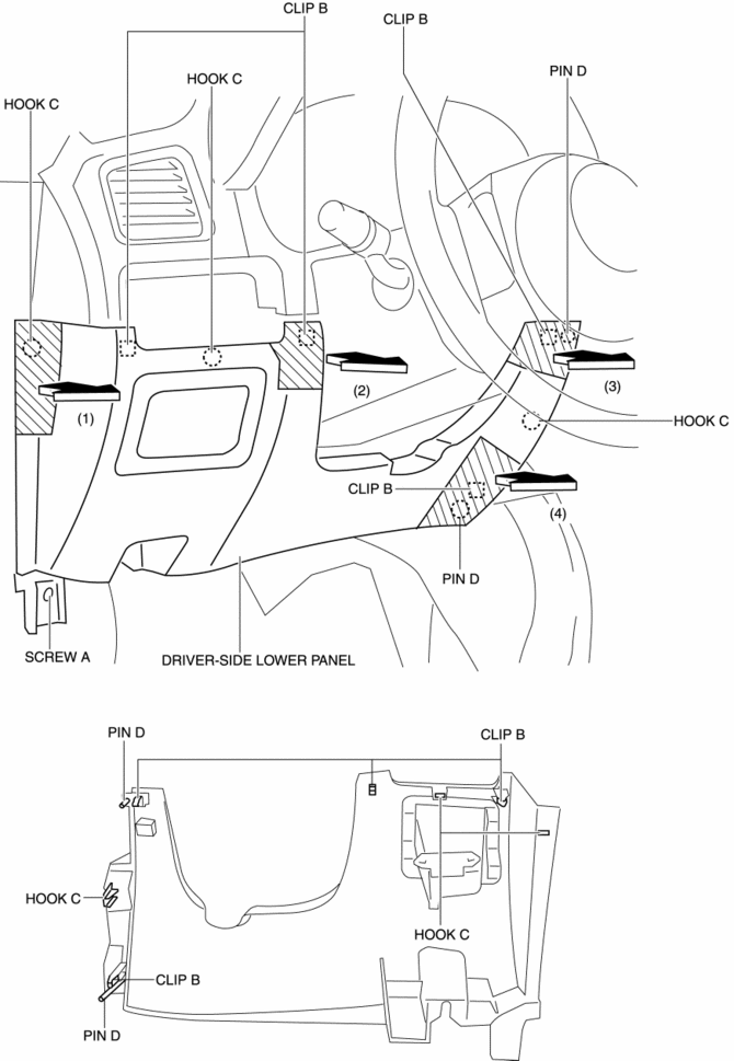
4. Take the shaded area shown in the figure, and pull the driver-side lower panel in the direction of the arrow in the order of (1), (2), (3), (4) and remove it while detaching clips B, hooks C and pins D.
5. Disconnect the car-navigation unit connector. (with car-navigation system)
6. Install in the reverse order of removal.
Passenger-side
Removal
1. Disconnect the negative battery cable.
2. Remove the following parts:
a. Passenger-side front scuff plate.
b. Passenger-side front side trim.
c. Glove compartment.
d. Decoration panel.
e. Dashboard under cover.
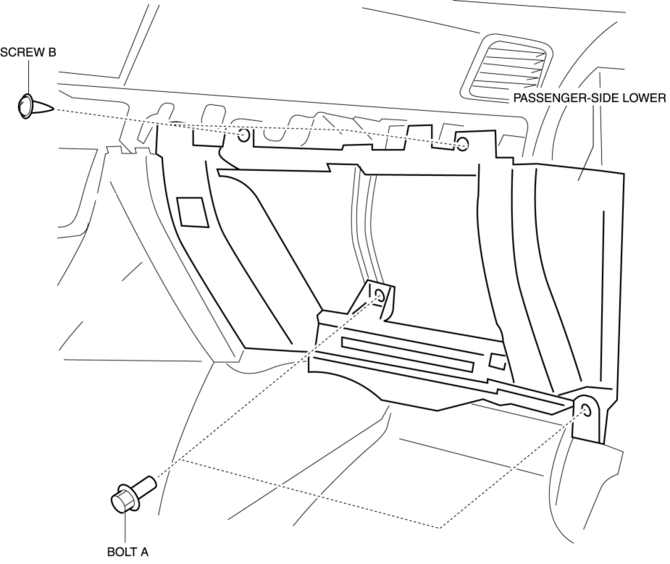
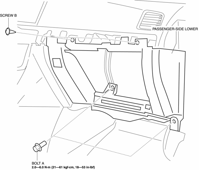
3. Remove bolts A.
4. Remove screws B.
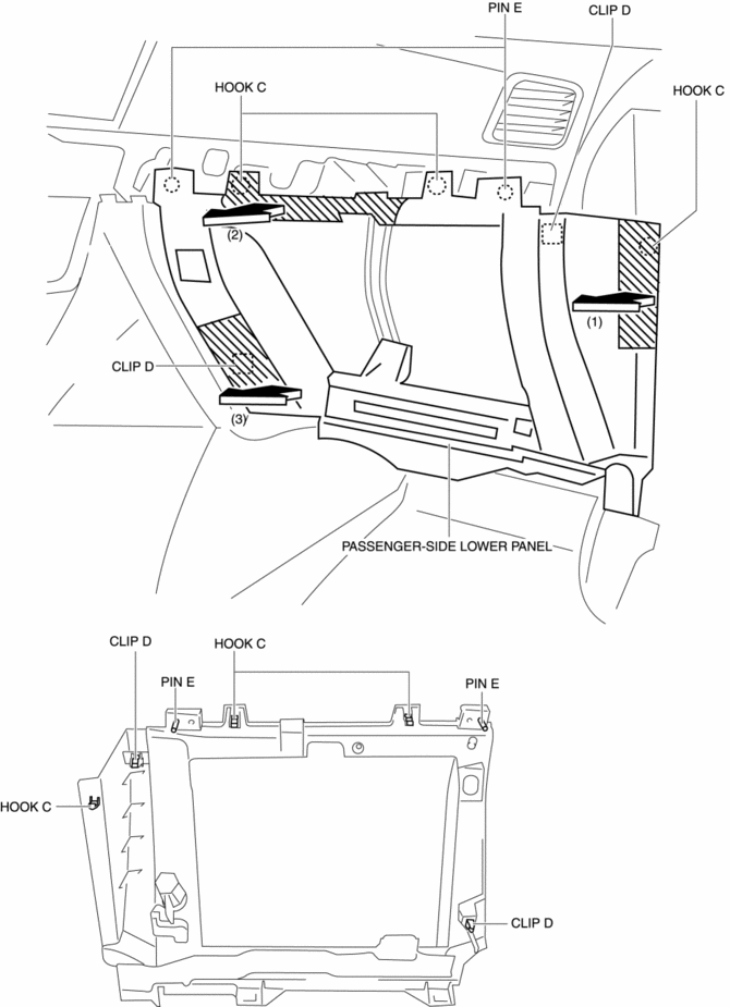
5. Take the shaded area shown in the figure, and pull the passenger-side lower panel in the direction of the arrow in the order of (1), (2), (3) and remove it while detaching hooks C, clips D and pins E.
Installation
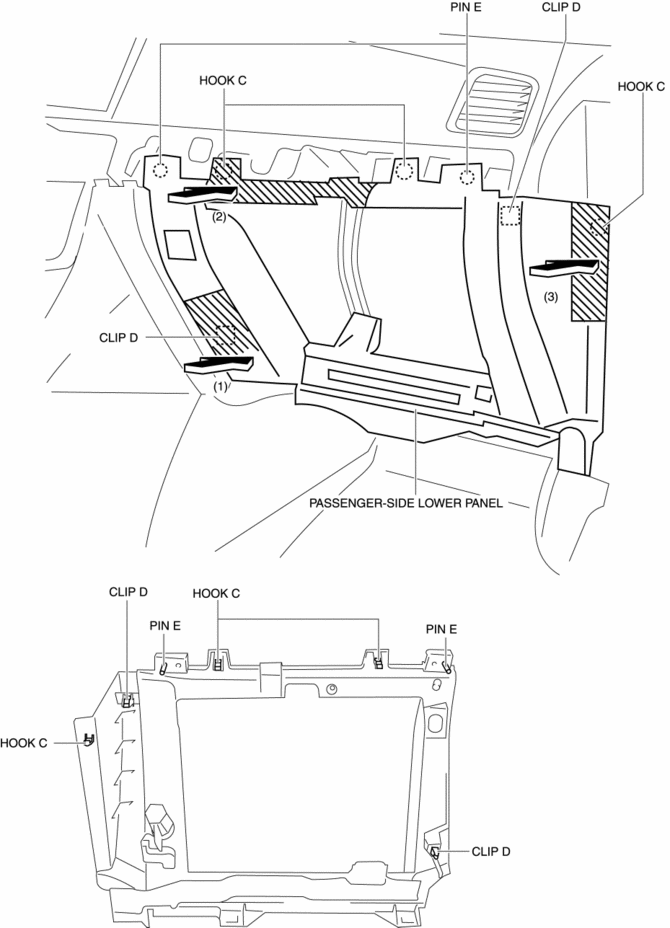
1. Install hooks C, clips D, and pins E while pressing the shaded area shown in the figure for the passenger-side lower panel in the direction of the arrow in the order of (1), (2), and (3).
2. Install screws B.
3. Install bolts A, and then install the passenger-side lower panel.
4. Install the following parts:
a. Dashboard under cover.
b. Decoration panel.
c. Glove compartment.
d. Passenger-side front side trim.
e. Passenger-side front scuff plate.
5. Connect the negative battery cable..
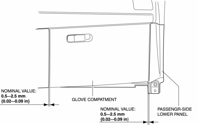
6. After installing the passenger-side lower panel and glove compartment, measure the clearance, and verify that the measurement value is within the specification shown in the figure.
-
If the measurement value is not within the specification after measuring the clearance between the passenger-side lower panel and glove compartment, adjust the passenger-side lower panel to the proper position..
Passenger-side lower panel adjustment
1. Remove the grove compartment..
2. Loosen bolts A.
-
If the passenger-side lower panel moves in the lateral direction when bolts A are loosened, go to the step 3 and 4.
-
If the passenger-side lower panel does not move in the lateral direction when bolts A are loosened, go to the step 5.
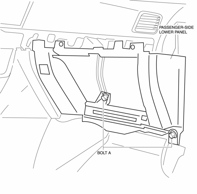
3. Remove bolts A.
4. Install bolts A in the order of (1), (2) shown in the figure.
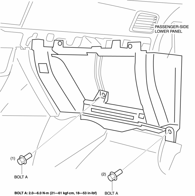
5. Install bolts A in the order of (1) and (2) while pressing the shaded area shown in the figure for the passenger-side lower panel.
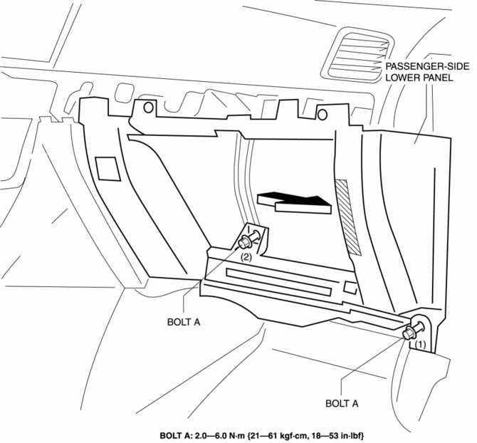
6. Install the glove compartment, measure the clearance between the glove compartment and passenger-side lower panel again, and verify that it is within the specification.
-
If it is not within the specification after measuring the clearance, repeat the adjustment procedure from Step 1.
 Interior Trim
Outline
A headliner equipped with a shock absorbing pad has been adopted.
The front and rear door trims are also equipped with shock absorbing pads.
Construction
...
 Plastic Parts Heat Resisting Temperature [Plastic Body Parts]
Part Name
Code
Material Name
Heat resisting
Temperature°C{°F}
Windshield molding
PVC
POLYVINYLCHLORI ...
Other materials:
Air Mix Actuator [Full Auto Air Conditioner]
Purpose
The air mix actuator moves the air mix door in the A/C unit to adjust the
temperature of the air blown from the air vent.
Function
Door open/close function
The air mix actuator drives the motor based on the signals from the climate
control unit and moves the air mi ...
Bsm Indicator Light Flashes While Not Under Bsm Indicator Light Flashing Conditions
(No Combination Switch Operation (Turn Signal Switch)) [Blind Spot Monitoring (Bsm)]
Description
BSM indicator light flashes while not under BSM indicator light-flashing
conditions (no combination switch operation (turn signal switch)
The BSM indicator light flashes despite not satisfying the BSM indicator
light flashing ...
Rain Sensor Removal/Installation
1. Disconnect the negative battery cable..
2. Spread open the rain sensor cover in the direction of the arrows (1) and disengage
tabs A to remove it.
3. Disconnect the rain sensor connector in the direction of the arrow (2).
4. Slide rain sensor tabs B in the direction of the arrow ...
