Mazda CX-5 Service & Repair Manual: Liftgate Garnish Removal/Installation
1. Disconnect the negative battery cable..
2. Remove the following parts:
a. Liftgate upper trim.
b. Liftgate side trim.
c. Liftgate recess.
d. Liftgate lower trim.
3. Disconnect the connectors.
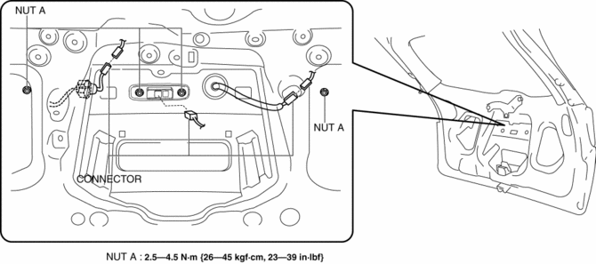
4. Remove nuts A.
5. Detach clips B shown in the figure.
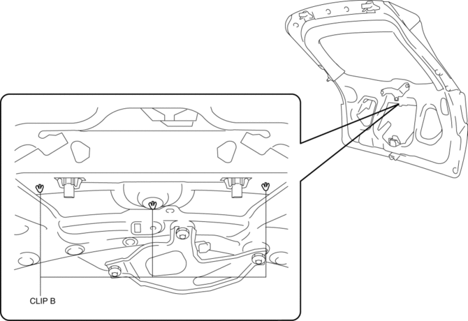
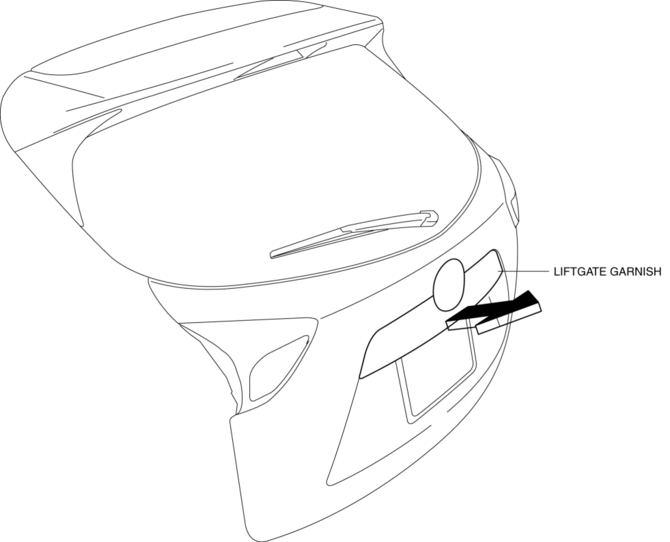
6. Remove the liftgate garnish shown in the figure.
7. Install in the reverse order of removal.
 Liftgate Adjustment
1. Measure the gap and height difference between the liftgate and the body.
2. Loosen the liftgate hinge installation bolts and adjust the liftgate.
Standard clearance
a: 5.2?7.2 mm { ...
 Liftgate Hinge Removal/Installation
1. Disconnect the negative battery cable..
2. Remove the following parts:
a. Rear scuff plate.
b. Trunk end trim.
c. Trunk side trim.
d. C-pillar trim.
e. D-pillar trim.
f. Liftgate.
3 ...
Other materials:
Receiver/Drier Removal/Installation
1. Disconnect the negative battery cable..
2. Discharge the refrigerant..
3. Remove the front under cover No.1..
4. Drain the engine coolant..
5. Remove the following parts:
a. Plug hole plate.
b. Air cleaner, air hose and fresh air duct component.
c. Coolant reserve tank.
d. Cooling ...
Presilencer
Purpose, Function
Reduces the exhaust noise.
Construction
The presilencer is installed to the rear of the TWC.
2WD
AWD
The presilencer consists of the filters, stuffing and wool-stainless.
2WD
AWD
...
Front Door Speaker Removal/Installation
Without Bose®
NOTE:
If the procedure is performed while holding the front door speaker cone,
it could deform the cone causing a malfunction. Therefore, perform the procedure
while holding any part other than the cone.
1. Disconnect the negative battery cable..
2. Remove the f ...
