Mazda CX-5 Service & Repair Manual: Glass Antenna Inspection
1. Disconnect the negative battery cable..
2. Partially peel back the seaming welt.
3. Remove the liftgate upper trim..
4. Disconnect antenna feeder No.3 connector..
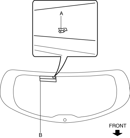
5. Visually inspect the glass antenna for damage.
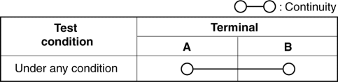
6. Verify that the continuity between the glass antenna terminals is as indicated in the table.
-
If not as indicated in the table, repair the glass antenna..
 Glass Antenna
Purpose, Function
The RDS (Radio Data System) converts radio broadcast waves to electric signals
and sends the signals to the audio unit.
Construction
An antenna with excellent ...
 Installation Of Radio System
The control modules and control unit have been designed with sufficient attention
to radio wave disturbances from the outside. However, observe the following precautions
when installing the radio ...
Other materials:
Fuel Injection Control System
Outline
Performs optimum fuel injection according to engine operation conditions.
The PCM determines the engine operation conditions based on the signals from
each input device and drives the fuel injectors at the optimal fuel injection
time (fuel injection amount) and the fuel ...
Crash Zone Sensor [Standard Deployment Control System]
Purpose
The crash zone sensor detects an impact during a frontal or frontal offset
collision to the vehicle.
Function
The crash zone sensor converts the detected impact to an electrical signal.
Construction
The crash zone sensor is built into the clutch sensor.
...
Vanity Mirror Illumination Inspection
1. Disconnect the negative battery cable..
2. Remove the sunvisor..
3. Verify that the continuity between the vanity mirror illumination terminals
is as indicated in the table.
If not as indicated in the table, replace the sunvisor.
...
