Mazda CX-5 Service & Repair Manual: Generator Control [Skyactiv G 2.0]
Outline
-
Idling stability has been improved by optimum control of generator voltage according to engine operation and electrical load conditions.
-
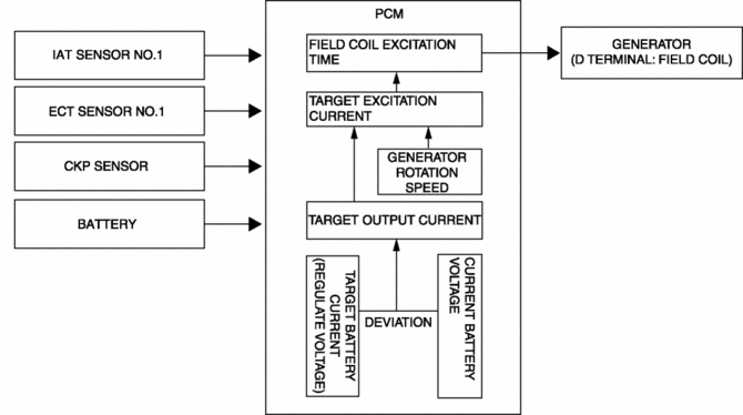
The PCM determines the engine operation and electrical load conditions based on the input signals from each control part and controls the energization time of the generator field coils.
Block Diagram

Operation
Determination method for target excitation current
-
The target excitation current is calculated from the generator target output amount (determined by intake air temperature, engine speed, and vehicle speed), and the actual generator rotation speed.
Determination method for field coil excitation time
-
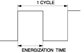
The PCM increases or decreases the field coil excitation current by sending a duty signal to the power transistor built into the generator.
-
The field coil energization current changes according to changes in the power transistor excitation time by changing the duty signal duty ratio. For example, when the battery positive voltage drops, the duty ratio of the duty signal sent to the power transistor is larger, increasing the field coil excitation current.

-
During deceleration fuel-cut, the PCM increases the generator voltage and stores electricity in the battery. At times other than deceleration, the PCM enables electric discharge from the battery to reduce the generator load.
-
Directly after the engine is started, the generator load is decreased by charging only to the necessary level according to the battery conditions in which the battery has not been charged to the maximum.
 Charging System [Skyactiv G 2.0]
Outline
Regulator-less generator (built-in power transistor) has been adopted.
A generator using two delta connection type stator coils has been adopted.
Structural View
Stru ...
 Generator Disassembly/Assembly [Skyactiv G 2.0]
CAUTION:
Melt the solder quickly, otherwise the diodes (rectifier) and regulator will
be damaged by excessive heat.
1. Disassemble in the order indicated in the table.
2. Assemble i ...
Other materials:
Rear Window Defroster/Outer Mirror Heater
Outline
Fogging is cleared from the rear window and outer mirror glass by heating
of the filament.
Structural view
System wiring diagram
Vehicles with full-auto air conditioner system
Vehicles with manual air conditioner system
Construction
Rear window defroster
...
Oil Cooler Removal/Installation
WARNING:
Hot engines and engine oil can cause severe burns. Turn off the engine and
wait until it and the engine oil have cooled.
A vehicle that is lifted but not securely supported on safety stands is dangerous.
It can slip or fall, causing death or serious injury. Never work ...
Blind Spot Monitoring (Bsm) Off Switch Inspection
1. Disconnect the negative battery cable..
2. Remove the BSM OFF switch..
3. Verify that the resistance between BSM OFF switches B and C is as indicated
in the table.
If the resistance cannot be verified as indicated in the table, replace the
cluster switch.
4. Apply batte ...
