Mazda CX-5 Service & Repair Manual: Fuel Gauge Sender Unit Removal/Installation [Awd]
WARNING:
-
Always keep sparks and flames away from fuel when servicing the fuel system. Fuel can be easily ignited which could cause serious injury or death, and damage to equipment.
-
Fuel line spills and leakage from the pressurized fuel system are dangerous. Fuel can ignite and cause serious injury or death and damage. Fuel can also irritate skin and eyes. To prevent this, always complete the Fuel Line Safety Procedure, while referring to the BEFORE SERVICE PRECAUTION.
-
A person charged with static electricity could cause a fire or explosion, resulting in death or serious injury. Before draining fuel, make sure to discharge static electricity by touching a vehicle.
CAUTION:
-
If the fuel gauge level indicates 3/4 or more, the fuel surface is higher than the fuel pump unit and fuel gauge sender unit installation surface. If servicing is performed under this condition, fuel leakage could result. Always drain the fuel before performing the operation and keep the fuel in the fuel tank at less than half.
Fuel Gauge Sender Unit (main)
NOTE:
-
For the fuel gauge sender unit removal/installation, refer to the fuel pump removal/installation because the fuel gauge sender unit is integrated with the fuel pump..
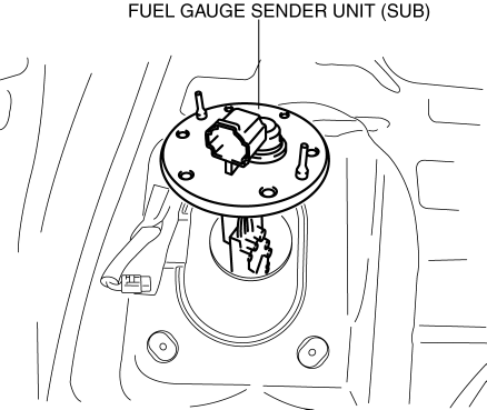
Fuel Gauge Sender Unit (sub)
1. Perform the "Fuel Line Safety Procedure" referring to the "BEFORE REPAIR PROCEDURE"..
2. If the fuel gauge level indicates 3/4 or more, refer to the "FUEL DRAINING PROCEDURE" and drain the fuel..
3. Remove the following parts:
a. Rear seat cushion (6:4 split type).
b. Rear seat under installation bolt (4:2:4 split type).
c. Rear scuff plate.
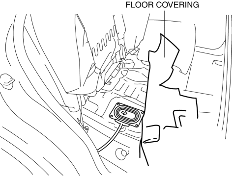
4. Partially peel back the floor covering.
5. Remove the screws.
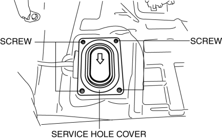
6. Remove the service hole cover.
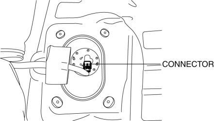
7. Disconnect the connector.
8. Remove the screws.
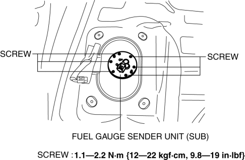
9. Remove the fuel gauge sender unit (sub).
10. Install in the reverse order of removal.
11. Perform the fuel leakage inspection referring to [AFTER SERVICE PRECAUTION]..
 Fuel Gauge Sender Unit Inspection [Awd]
Fuel gauge sender unit (main)
NOTE:
For the fuel gauge sender unit removal/installation, refer to the fuel pump
removal/installation because the fuel gauge sender unit is integrated with t ...
 Planetary Gear [Fw6 A EL, Fw6 Ax EL]
Purpose/Function
The planetary gear is a mechanism which shifts the drive force from the engine.
The planetary gear consists of multiple gears which rotate individually while
revolving. B ...
Other materials:
Liftgate Hinge Removal/Installation
1. Disconnect the negative battery cable..
2. Remove the following parts:
a. Rear scuff plate.
b. Trunk end trim.
c. Trunk side trim.
d. C-pillar trim.
e. D-pillar trim.
f. Liftgate.
3. Remove fasteners.
4. While partially peeling back the rear part of the headliner, remove nut ...
Exhaust System
Purpose, Outline
A 4-2-1 exhaust system has been adopted which reduces residual gas in the
cylinders using the scavenging effect and contributes to a high compression
ratio.
The loop structure of the exhaust pipes for the 4-2-1 system takes up less
space.
Structural Vie ...
Windshield Wiper Motor
Purpose
The windshield wiper motor transmits rotation force to the windshield wiper
link to operate the windshield wiper arms and blades.
Function
The windshield wiper motor operates using the current from the front body
control module (FBCM) which is input according to the ...
