Mazda CX-5 Service & Repair Manual: Fuel Gauge Sender Unit Inspection [Awd]
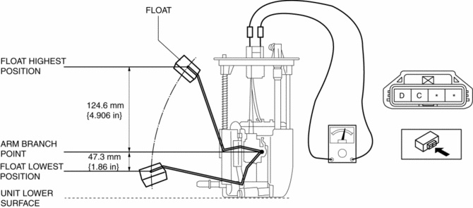
Fuel gauge sender unit (main)
NOTE:
-
For the fuel gauge sender unit removal/installation, refer to the fuel pump removal/installation because the fuel gauge sender unit is integrated with the fuel pump..
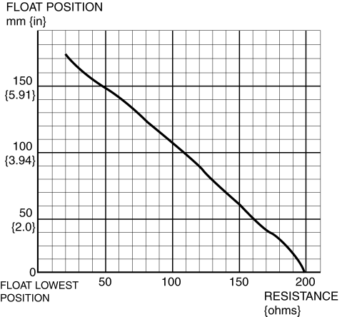
1. Verify that the resistance at fuel gauge sender unit (main) terminals D and C is as indicated in the table according to the height of the float.
-
If not as indicated in the table, replace the fuel gauge sender unit (main).
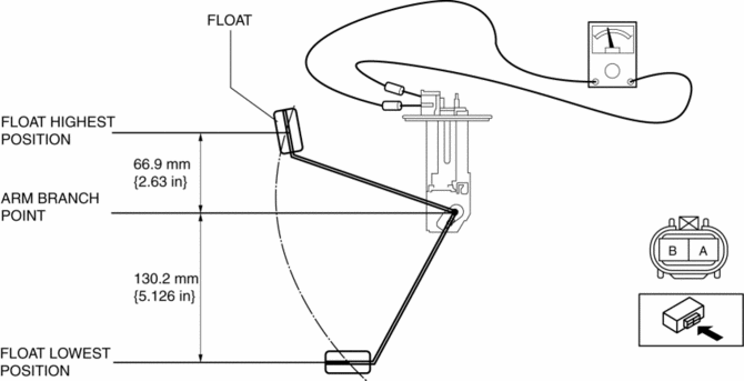
Fuel gauge sender unit (sub)
1. Remove the fuel gauge sender unit (sub)..
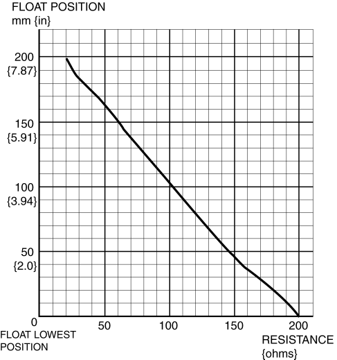
2. Verify that the resistance at fuel gauge sender unit (sub) terminals B and A is as indicated in the table according to the height of the float.
-
If not as indicated in the table, replace the fuel gauge sender unit (sub).
 Fuel Gauge Sender Unit Inspection [2 Wd]
NOTE:
For the fuel gauge sender unit removal/installation, refer to the fuel pump
removal/installation because the fuel gauge sender unit is integrated with the
fuel pump..
1. Veri ...
 Fuel Gauge Sender Unit Removal/Installation [2 Wd]
WARNING:
Always keep sparks and flames away from fuel when servicing the fuel system.
Fuel can be easily ignited which could cause serious injury or death, and damage
to equipment.
...
Other materials:
Instrumentation/Driver Info.
Outline
An LCD has been adopted to the instrument cluster which displays the ambient
temperature, trip computer, and odometer/tripmeter.
A blind spot monitoring (BSM) system has been adopted which notifies the
driver of vehicles approaching from behind on the left or right adjac ...
Electric Variable Valve Timing Actuator Inspection
WARNING:
A hot engine can cause severe burns. Turn off the engine and wait until it
is cool before servicing.
CAUTION:
Do not disassemble the electric variable valve timing actuator because it
is a precision unit.
1. Disconnect the negative battery cable..
2. Remo ...
Cowl Upper Plate Installation [Panel Replacement]
Symbol Mark
Installation Procedure
1. When installing new parts, measure and adjust the body as necessary to conform
with standard dimensions.
2. Drill holes for the plug welding before installing the new parts.
3. After temporarily installing new parts, make sure the related parts fit p ...
