Mazda CX-5 Service & Repair Manual: Fuel Gauge
Purpose
-
The fuel gauge notifies the user of the amount of remaining fuel.
Function
-
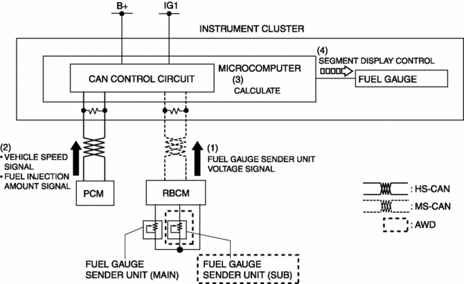
The instrument cluster calculates the amount of fuel in the fuel tank based on the following CAN signals and displays the fuel gauge segments.
-
Fuel gauge sender unit voltage signal sent from rear body control module (RBCM)
-
Fuel injection amount signal, vehicle speed signal sent from PCM
Fuel gauge flicker prevention function
-
When the instrument cluster determines that the vehicle is being driven, it retards the response with which the calculated amount of fuel is reflected to the fuel gauge. As a result, fuel gauge flicker caused by the variation of fuel surface during driving is prevented.
Refuel determination function
-
If the amount of fuel is changed by 5 L {1 US gal, 1 Imp gal}/2 L {0.5 US gal, 0.4 Imp gal}*1 or more while the vehicle is stopped, the instrument cluster determines that the vehicle is refueled and displays the fuel gauge segments based on the fuel gauge sender unit voltage signal from the rear body control module (RBCM).
Construction
-
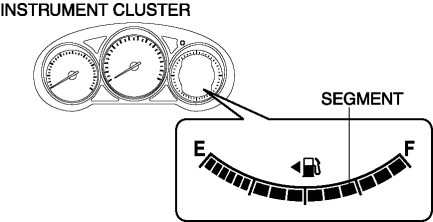
The fuel gauge is displayed in the LCD of the instrument cluster.
-
The fuel gauge is consists of 15 segments.

Operation
-
When the ignition is switched ON (engine off or on), the rear body control module (RBCM) converts the resistance from the fuel gauge sender unit to voltage and sends it to the instrument cluster as a fuel gauge sender unit voltage signal (1).
-
The instrument cluster receives the fuel gauge sender unit voltage signal from the rear body control module (RBCM), and it also receives the fuel injection amount signal and vehicle speed signal from the PCM (2).
-
The instrument cluster calculates the amount of fuel in the fuel tank based on the signals (3).
-
The instrument cluster displays/turns off the fuel gauge segments according to the calculation result (4).

Fail-safe
-
Function not equipped.
 Ambient Temperature Display Switching Procedure
NOTE:
When the ambient temperature display is switched, the set A/C cabin temperature
display is also changed.
...
 Fuel Gauge Sender Unit Inspection [2 Wd]
NOTE:
For the fuel gauge sender unit removal/installation, refer to the fuel pump
removal/installation because the fuel gauge sender unit is integrated with the
fuel pump..
1. Veri ...
Other materials:
Windshield Wipers and Washer
The ignition must be switched ON.
WARNING
Use only windshield washer fluid or plain water in the reservoir:
Using radiator antifreeze as washer fluid is dangerous. If sprayed on the windshield,
it will dirty the windshield, affect your visibility, and could result in an accident.
Only use wind ...
On/Off Solenoid Removal/Installation [Fw6 A EL, Fw6 Ax EL]
WARNING:
A hot transaxle and ATF can cause severe burns. Turn off the engine and wait
until they are cool.
Always wear protective eye wear when using the air compressor. If the air
compressor is used, any particles of dirt or soiling could spatter and get into
the eyes.
...
Front Fog Light Removal/Installation
1. Disconnect the negative battery cable..
2. Remove the screws and bolt.
3. Pull up the front under cover No.1 and remove the mudguard screw shown in
the figure.
4. Disconnect the connector.
5. While pressing the clip tab in the direction of the arrow (1) shown in the
figure ...
