Mazda CX-5 Owners Manual: Fuel-Filler Lid and Cap
WARNING
When removing the fuel-filler cap, loosen the cap slightly and wait for any hissing to stop. Then remove it:
Fuel spray is dangerous. Fuel can burn skin and eyes and cause illness if ingested. Fuel spray is released when there is pressure in the fuel tank and the fuel-filler cap is removed too quickly.
Before refueling, stop the engine, and always keep sparks and flames away from the filler neck:
Fuel vapor is dangerous. It could be ignited by sparks or flames causing serious burns and injuries.
Additionally, use of the incorrect fuelfiller cap or not using a fuel-filler cap may result in fuel leak, which could result in serious burns or death in an accident.
CAUTION
(U.S.A. and Canada) Always use only a genuine Mazda fuel-filler cap or an approved equivalent, available at an Authorized Mazda Dealer. The wrong cap can result in a serious malfunction of the fuel and emission control systems. It may also cause the check engine light in the instrument cluster to illuminate.
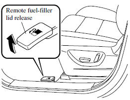
Fuel-Filler Lid
To open, pull the remote fuel-filler lid release.
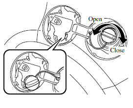
Fuel-Filler Cap
To remove the fuel-filler cap, turn it counterclockwise.
Attach the removed cap to the inner side of the fuel lid.
To close the fuel-filler cap, turn it clockwise until a click is heard.
CAUTION
(U.S.A. and Canada) If the check fuel cap warning light illuminates, the fuel-filler cap may not be properly installed. If the warning light illuminates, park your vehicle safely off the right-of-way, remove the fuel-filler cap and reinstall it correctly. After the cap has been correctly installed, the fuel cap warning light may continue to illuminate until a number of driving cycles have been completed. A drive cycle consists of starting the engine (after four or more hours with the engine off) and driving the vehicle on city and highway roads.
Continuing to drive with the check fuel cap warning light illuminated could cause the check engine light to illuminate as well.
 Fuel and Engine Exhaust Precautions
Fuel Requirements
Vehicles with catalytic converters or oxygen sensors must use ONLY UNLEADED FUEL,
which will reduce exhaust emissions and keep spark plug fouling to a minimum.
Your Mazda will pe ...
 Steering Wheel
Steering Wheel
WARNING
Never adjust the steering wheel while the vehicle is moving: Adjusting the steering
wheel while the vehicle is moving is dangerous.
Moving it can very easily cause the driv ...
Other materials:
Oil Control Valve (OCV) Inspection [Skyactiv G 2.0]
Coil Resistance Inspection
1. Disconnect the negative battery cable..
2. Remove the plug hole plate..
3. Disconnect the OCV connector.
4. Measure the resistance between terminals A and B using an ohmmeter.
OCV coil resistance
6.9—7.5 ohms [20°C {68°F}]
If ...
R 3 5 Brake [Fw6 A EL, Fw6 Ax EL]
Purpose/Function
The R-3-5 brake operates in 3GR, 5GR and in reverse to lock the reduction
internal gear against rotation.
Construction
The R-3-5 brake consists of the following parts shown in the figure.
The driven plate of the R-3-5 brake does not rotate be ...
Front Drive Shaft (Double Offset Joint) Disassembly/Assembly
1. Disassemble in the order indicated in the table.
2. Assemble in the reverse order of disassembly.
1
Boot band (transaxle side)
(See FRONT DRIVE SHAFT (TRIPOD JOINT) DISASSEMBLY/ASSEMBLY.)
2
Clip
(See Clip Disassembly Note.)
...
